Search filter
Filter
Reset- Installation drawing (725)
- Product data sheet (717)
- Tender texts (252)
- Installation instructions (244)
- Product scale drawing (119)
- 3D model (113)
- Certificate (79)
- Declarations of performance (74)
- Cable plan (67)
- Environmental declaration (44)
- Declaration of conformity (39)
- Wiring diagram (29)
- User manual (23)
- Supplementary sheet (17)
- Flyer/folder (17)
- Product brochure (13)
- Inspection certificate (8)
- Type examination certificate (6)
- Software (4)
- T&C / Data Protection (4)
- Supplier information (4)
- Product shot (3)
- Safety analysis (1)
- Evaluation/comment (1)
- Customer information (1)
2604 results found

E 170 scissor drive
(DWG | 894 KB)
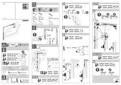
OL 90 N / OL 95 vertical gear Fz 91
3 Fz 91 min. 1,8 mm 030364 030381 135479 085349 B min. 62 H 4,2 x L DIN 7972 / DIN 7982 Fz … mm … ... … Nm D Ø 2,5 mm Ø 3,5 mm 030364 030381 135479 085349 … 150 152794-01 W … 3 min. … x S … x 35 4,2 x L DIN 97 / DIN 7972 / DIN 7997 DIN 7982 … La Ø 3,5 mm … 2 … 5 … 4 … 1 … 030364 030381 135479 085349 030364 030381 135479 085349 … 5 … 159976-.. … www.geze.de … Lb = L + 116 mm Lb 030381 (OL 90 N) 085349 (OL 95) 40444-EP-008 40445-EP-05 + … 9 ... 13 D min. [mm] X [mm] 12 D+9 14 max. [kg/m²] OL 90 N OL 95 40444-EP-008 - - - - 40445-EP-05 D + 0444-EP-008 - - - - 40445-EP-05 … mm 14 D + 14 … 030364 030381 135479 085349 … 030364 030381 135479 085349 030364 030381 135479 085349 LA2 [mm] CA – 152 … 1 Ø 2,5 mm Ø 3,5 mm 030364 030381 135479 085349 … a [mm] … G L D OL 90 N OL 95 112 L min. … 030364 (OL 90 N) 135479 (OL 95) 15 G = min. 360 min. 62 112 150 15 f1 min. 180 … Lb … 14 LA2 [mm] L + 346 16 15 … 35 … 2 17 … 4 x 16 Fz 91 + … ... 14 40444-EP-011 18 D … x 35 DIN 97 / DIN 7997 Ø 2,5 mm 4,2 x L DIN 7972 / DIN 7982 Ø 3,5 mm 35 ~ 300 min. … x ~ 300 min. 1,8 mm D 35 Ø 2,5 mm Ø 3,5 mm 4,2 x L DIN 7972 / DIN 7982 Ø 3,5 mm D min. = 10 mm D min. = 14 mm GEZE GmbH Reinhold-Vöster-Straße 21–29 71229 Leonberg Germany Tel.: 0049 7152 203 … Fax: 0049 7152 203 310 www.geze.com … x 20
(PDF | 9 MB)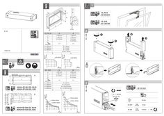
E 212
1 X D Y + OL 90 N ID 030364 + OL 320 ID 130738 b a ü E 212 i OL 90 N A B a b Y X ≥ 600 mm ≥ 250 mm D +23 mm - ≥ 380 mm ≥ 250 mm D +9 mm D +23 mm ≤4 ≤3 b ≥ 250 mm b ≥ 300 mm b ≥ 400 mm i 153444-01 kg/m2 kg/m2 A B a b Y X ≥ 890 mm ≥ 400 mm D +19 mm - ≥ 680 mm ≥ 400 mm D +13 mm D +19 mm ≤4 ≤2 40444-EP-004 (OL 90 N) 40424-EP-029 (OL 320) b ≥ 400 mm b ≥ 500 mm b ≥ 600 mm b ≥ 800 mm … D = 23 mm D = 21/23 mm D = 19/21/23 mm D = 17/19/21/23 mm A + B kg/m2 B … a OL 320 kg/m2 ≥ 500 mm (OL 90 N) ≥ 540 mm (OL 320) + 40444-EP-003 (OL 90 N) 40424-EP-030 (OL 320) … B a + … 1 D = 16 mm D = 14 mm D = 12 mm 10 mm - 60 mm A A … ID 151531 1x = 0,8 mm 42f52g70 - a a + 52 mm OL 90 N max. 52 mm … mm OL 320 max. 70 mm +16 mm = 20x … 4 … 1 … OL 90 N … 7 … 1 … OL 320 175 … + 175 … 2 [mm] [mm] OL 320 … D-6 D-6 min … 42 162 172 122 134 215 45 178 190 135 146 50 241 50 200 211 153 164 55 264 54 219 227 168 172 60 285 66 306 70 320 … mm OL 320 … ID 151531 GEZE GmbH Reinhold-Vöster-Strasse 21–29 71229 Leonberg Germany Tel.: 0049 7152 203 … Fax: 0049 7152 203 310 www.geze.com OL90 max 198 … + OL90 min 45 OL 90 N … mm OL95 max 42 max. … OL95 min
(PDF | 3 MB)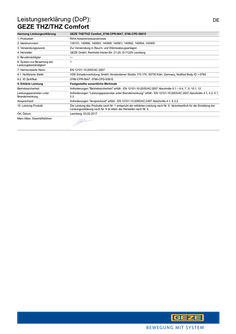
Declaration of performance (DoP): GEZE THZ / THZ Comfort smoke and heat extraction system SHEV control panel
Leistungserklärung (DoP): GEZE THZ/THZ Comfort DE Kennung Leistungserklärung GEZE THZ/THZ Comfort_0786-CPR-0647, 0786-CPD-50615 1. Produktart RWA Notstromsteuerzentrale 2. Identnummern 139151, 140906, 140903, 140900, 140901, 140902, 140904, 140905 3. Verwendungszweck Zur Verwendung in Rauch- und Wärmeabzugsanlagen 4. Hersteller GEZE GmbH, Reinhold-Vöster-Str. 21-29, D-71229 Leonberg 5. Bevollmächtigter --- 6. System zur Bewertung der Leistungsbeständigkeit … 7. Harmonisierte Norm EN 12101-10:2005/AC:2007 … . Notifizierte Stelle VDS Schadenverhütung GmbH, Amsterdamer Straße 172-174, 50735 Köln, Germany, Notified Body ID = 0786 … . ID Zertifikat 0786-CPR-0647, 0786-CPD-50615 9. Erklärte Leistung Festgestellte wesentliche Merkmale Betriebssicherheit Anforderungen "Betriebssicherheit" erfüllt - EN 12101-10:2005/AC:2007 Abschnitte … – … , 7, 9, … , 12 Leistungsparameter unter Brandeinwirkung Anforderungen "Leistungsparameter unter Brandeinwirkung" erfüllt - EN 12101-10:2005/AC:2007 Abschnitte … , … , … , … Ansprechzeit Anforderungen "Ansprechzeit" erfüllt - EN 12101-10:2005/AC:2007 Abschnitte … , … .2 10. Leistung Produkt Die Leistung des Produkts nach Nr. … entspricht der erklärten Leistung nach Nr. 9. Verantwortlich für die Erstellung der Leistungserklärung nach Nr. … ist allein der Hersteller nach Nr. 4. Ort, Datum Leonberg, … .2017 Marc Alber, Geschäftsführer Declaration of Performance (DoP): GEZE THZ/THZ Comfort EN ID for Declaration of Performance GEZE THZ/THZ Comfort_0786-CPR-0647, 0786-CPD-50615 1. Type of product RWA emergency power control unit 2. Identity numbers 139151, 140906, 140903, 140900, 140901, 140902, 140904, 140905 3. Intended use For use in smoke and heat extraction systems 4. Manufacturer GEZE GmbH, Reinhold-Vöster-Str. 21-29, D-71229 Leonberg 5. Authorised signatory --- 6. System for evaluating performance reliability … 7. Harmonised standard EN 12101-10:2005/AC:2007 … . Notified office VDS Schadenverhütung GmbH, Amsterdamer Straße 172-174, 50735 Köln, Germany, Notified Body ID = 0786 … . ID certificate 0786-CPR-0647, 0786-CPD-50615 9. Declared performance Essential characteristics determined Operational safety “Operational safety” requirements met - EN 12101-10:2005/AC:2007 sections … – … , 7, 9, … , and 12 Performance parameters under the effect of fire “Performance parameters under the effect of fire” requirements met - EN 12101-10:2005/AC:sections … , … , … , … Response time “Response time” requirements met - EN 12101-10:2005/AC:2007 sections … , … .2 10. Product performance The performance of the product specified under No. … corresponds to the declared performance according to No. 9. The manufacturer under No. … is solely responsible for preparing the declaration of performance according to No. 9. Place, date Leonberg, … .2017 Marc Alber, Managing Director декларация за мощност (DoP): GEZE THZ/THZ Comfort BG Означение декларация за мощност GEZE THZ/THZ Comfort_0786-CPR-0647, 0786-CPD-50615 1. Вид продукт Централен команден блок за отвеждане на дим и топлина 2. Идентификационен номер 139151, 140906, 140903, 140900, 140901, 140902, 140904, 140905 3. Цел на използване Използва се в системи за отвеждане на дим и топлина 4. Производител GEZE GmbH, Reinhold-Vöster-Str. 21-29, D-71229 Leonberg 5. Упълномощено лице --- 6. Система за оценка на устойчивостта при работа … 7. Хармонизиран стандарт EN 12101-10:2005/AC:2007 … . Нотифициран орган VDS Schadenverhütung GmbH, Amsterdamer Straße 172-174, 50735 Köln, Germany, Notified Body ID = 0786 … . ID сертификат 0786-CPR-0647, 0786-CPD-50615 9. Декларирана мощност Установени съществени белези Безопасност на експлоатацията Изпълнени изисквания „безопасност на експлоатацията“ - EN 12101-10:2005/AC:2007 раздели … – … , 7, 9, … , и 12 Работни параметри при въздействие от пожар Изпълнени изисквания „работни параметри при въздействие от пожар“ - EN 12101-10:2005/AC:2007 раздели … , … , … , … Време за задействане Изпълнени изисквания „време за въздействие“ - EN 12101-10:2005/AC:2007 раздели … , … .2 10. Мощност на продукта Мощността на продукта според № … съответства на декларираната мощност според № 9. Отговорен за съставяне на декларация за мощност според № … е единствено производителят според № 4. Населено място, дата Leonberg, … .2017 Херман Албер, търговски директор Ydeevnedeklaration (DoP): GEZE THZ/THZ Comfort Identifikation ydeevnedeklaration GEZE THZ/THZ Comfort_0786-CPR-0647, 0786-CPD-50615 1. Produktart RWA Nødstrømskontrolcentral 2. Id-numre 139151, 140906, 140903, 140900, 140901, 140902, 140904, 140905 3. Anvendelsesformål Til anvendelse i røg- og varmeudsugningsanlæg 4. Producent GEZE GmbH, Reinhold-Vöster-Str. 21-29, D-71229 Leonberg 5. Befuldmægtiget --- 6. System til vurdering af ydelsesbestandigheden … 7. Harmoniseret standard EN 12101-10:2005/AC:2007 … . Notificeret organ VDS Schadenverhütung GmbH, Amsterdamer Straße 172-174, 50735 Köln, Germany, Notified Body ID = 0786 … . Id certifikat 0786-CPR-0647, 0786-CPD-50615 9. Deklareret ydeevne Konstaterede væsentlige egenskaber Driftssikkerhed Kravene "Driftssikkerhed" opfyldt - EN 12101-10:2005/AC:2007 Afsnit … – … , 7, 9, … , og 12 Ydelsesparametre under brandpåvirkning Kravene "Ydelsesparametre under brandpåvirkning" opfyldt - EN 12101-10:2005/AC:2007Afsnit … , … , … , … Reaktionstid Kravene "Reaktionstid" opfyldt - EN 12101-10:2005/AC:2007 Afsnit … , … .2 10. Produktets ydeevne Produktets ydeevne iht. nr. … svarer til den deklarerede ydeevne iht. nr. 9. Ansvarlig for udarbejdelsen af ydeevnedeklarationen iht. nr. … er alene producenten iht. nr. 4. Sted, dato Leonberg, … .2017 Marc Alber, forretningsfører DA Toimimisviis (DoP): GEZE THZ/THZ Comfort ET Tähis / toimimisviis GEZE THZ/THZ Comfort_0786-CPR-0647, 0786-CPD-50615 1. Toode RWA (suitsu ja kuumuse eemaldussüsteemi) avariitoiteallikas 2. Tootenumber 139151, 140906, 140903, 140900, 140901, 140902, 140904, 140905 3. Kasutusotstarve Mõeldud kasutamiseks suitsu ja kuumuse eemaldussüsteemides 4. Tootja GEZE GmbH, Reinhold-Vöster-Str. 21-29, D-71229 Leonberg 5. Esindaja --- 6. Süsteem töökindluse hindamiseks … 7. Harmoniseeritud norm EN 12101-10:2005/AC:2007 … . Teatatud asukoht VDS Schadenverhütung GmbH, Amsterdamer Straße 172-174, 50735 Köln, Germany, Notified Body ID = 0786 … . ID-sertifikaat 0786-CPR-0647, 0786-CPD-50615 9. Deklareeritud jõudlus Kindlakstehtud olulised tunnused Töökindlus Vastab nõuetele „Töökindlus” – standardi EN 12101-10:2005/AC:2007 punktid … – … , 7, 9, … ja 12 Tööparameetrid tulekahju korral Vastab nõuetele „Tööparameetrid tulekahju korral” – standardi EN 12101-10:2005/AC:2007 punktid … , … , … ja … Reaktsiooniaeg Vastab nõuetele „Reaktsiooniaeg” – standardi EN 12101-10:2005/AC:2007 punktid … ja … .2 10. Toote jõudlus Toote jõudlus (nr 1) on kooskõlas deklareeritud jõudlusega (nr 9). Jõudlusdeklaratsiooni (nr 9) koostamise eest vastutab ainult tootja (nr 4). Koht, kuupäev Leonberg, … .2017 Marc Alber, ärijuht Toimintoselvitys (DoP): GEZE THZ/THZ Comfort Tunnus toimintoselvitys GEZE THZ/THZ Comfort_0786-CPR-0647, 0786-CPD-50615 1. Tuotetyyppi RWA-varavoimaohjauskeskus 2. Tunnusnumerot 139151, 140906, 140903, 140900, 140901, 140902, 140904, 140905 3. Käyttötarkoitus Savun- ja lämmönpoistolaitteistot 4. Valmistaja GEZE GmbH, Reinhold-Vöster-Str. 21-29, D-71229 Leonberg 5. Valtuutettu --- 6. Järjestelmä vakaan toimivuuden arviointiin … 7. Sovellettu normi EN 12101-10:2005/AC:2007 … . Ilmoitettu paikka VDS Schadenverhütung GmbH, Amsterdamer Straße 172-174, 50735 Köln, Germany, Notified Body ID = 0786 … . ID-varmenne 0786-CPR-0647, 0786-CPD-50615 9. Selvitetty toiminto Määritetyt olennaiset ominaisuudet Käyttöturvallisuus Vaatimukset ”Käyttöturvallisuus” täytetty – EN 12101-10:2005/AC:2007 luvut … – … , 7, 9, … , ja 12 Suorituskykyparametri tulelle altistumisessa Vaatimukset ”Suorituskykyparametri tulelle altistumisessa” täytetty – EN 12101-10:2005/AC: luvut … , … , … , … Vasteaika Vaatimukset ”Vasteaika” täytetty – EN 12101-10:2005/AC:2007 luvut … , … .2 10. Tuotteen suorituskyky Tuotteen suorituskyky numeron … mukaan vastaa numerossa … selvitettyä toimintoa. Valmistaja on yksin vastuussa numeron … mukaan laaditusta toimintoselvityksestä. Paikka, päivämäärä Leonberg, … .2017 Marc Alber, toimitusjohtaja FI Déclaration des performances (DoP): GEZE THZ/THZ Comfort FR Identification Déclaration des performances GEZE THZ/THZ Comfort_0786-CPR-0647, 0786-CPD-50615 1. Type de produit Centrale de commande de secours RWA 2. Numéros d'identification 139151, 140906, 140903, 140900, 140901, 140902, 140904, 140905 3. Usage prévu Pour une utilisation dans les installations d’extraction de fumée et de chaleur 4. Fabricant GEZE GmbH, Reinhold-Vöster-Str. 21-29, D-71229 Leonberg 5. Mandataire --- 6. Système d'évaluation de la constance des performances … 7. Norme harmonisée EN 12101-10:2005/AC:2007 … . Autorité notifiante VDS Schadenverhütung GmbH, Amsterdamer Straße 172-174, 50735 Köln, Germany, Notified Body ID = 0786 … . Certificat ID 0786-CPR-0647, 0786-CPD-50615 9. Performances déclarées Principales caractéristiques constatées Sécurité de fonctionnement Exigences « Sécurité de fonctionnement » remplies - EN 12101-10:2005/AC:2007 sections … – … , 7, 9, … , et 12 Paramètres de performance sous l’effet d'un incendie Exigences « Paramètres de performance sous l’effet d’un incendie » remplies - EN 12101-10:2005/AC:2007 sections … , … , … , … Temps de réaction Exigences « Temps de réaction » remplies - EN 12101-10:2005/AC:2007 sections … , … .2 10. Performances du produit Les performances du produit indiqué au n° … correspondent aux performances déclarées au n° 9. Le fabricant identifié au n°4 est seul responsable de l'établissement de la déclaration des performances selon le n° 9. Lieu, date Leonberg, … .2017 Marc Alber, gérant Δήλωση ισχύος (DoP): GEZE THZ/THZ Comfort EL Χαρακτηρισμός Δήλωση ισχύος GEZE THZ/THZ Comfort_0786-CPR-0647, 0786-CPD-50615 1.Τύπος προϊόντος Κέντρο ελέγχου ρεύματος ανάγκης RWA 2.Αριθμοί αναγνώρισης 139151, 140906, 140903, 140900, 140901, 140902, 140904, 140905 3.Σκοπός χρήσης Για τη χρήση σε συστήματα εξαερισμού για την απαγωγή καπνού και θερμότητας 4.Κατασκευαστής GEZE GmbH, Reinhold-Vöster-Str. 21-29, D-71229 Leonberg 5.Πληρεξούσιος --- 6.Σύστημα αξιολόγησης σταθερότητας ισχύος … 7.Εναρμονισμένο πρότυπο EN 12101-10:2005/AC:2007 … .Κοινοποιημένος φορέας VDS Schadenverhütung GmbH, Amsterdamer Straße 172-174, 50735 Köln, Germany, Notified Body ID = 0786 … .Πιστοποιητικό αναγνωριστικού αριθμού 0786-CPR-0647, 0786-CPD-50615 9.Δηλωθείσα ισχύς Καταγεγραμμένα βασικά χαρακτηριστικά Ασφάλεια λειτουργίας Πληρούνται οι απαιτήσεις "Ασφάλεια λειτουργίας" - EN 12101-10:2005/AC:2007 Μέρος … – … , 7, 9, … , και 12 Παράμετροι επίδοσης υπό την επίδραση πυρκαγιάς Πληρούνται οι απαιτήσεις "Παράμετροι επίδοσης υπό την επίδραση πυρκαγιάς" - EN 12101-10:2005/AC:2007 Μέρος … , … , … , … Χρόνος αντίδρασης Πληρούνται οι απαιτήσεις "Χρόνος αντίδρασης" - EN 12101-10:2005/AC:2007 Μέρος … , … .2 10.Ισχύς προϊόντος Η ισχύς του προϊόντος κατά τον αρ. … αντιστοιχεί στη δηλωθείσα ισχύ κατά τον αρ. 9.Υπεύθυνος για τη σύνταξη της δήλωσης ισχύος κατά τον αρ. … είναι αποκλειστικά ο κατασκευαστής κατά τον αρ. 4. Τόπος, Ημερομηνία Leonberg, … .2017 Marc Alber, Διευθύνων σύμβουλος Dearbhú Feidhmíochta (DoP): GEZE THZ/THZ Comfort GA Aitheantóir Dearbhú Feidhmíochta GEZE THZ/THZ Comfort_0786-CPR-0647, 0786-CPD-50615 1. Cineál táirge Lárionad rialú cumhachta éigeandála RWA 2. Uimhreacha aitheantais 139151, 140906, 140903, 140900, 140901, 140902, 140904, 140905 3. Úsáid bheartaithe Chun úsáide i ngléasraí eastarraingthe deataigh agus teasa 4. Déantóir GEZE GmbH, Reinhold-Vöster-Str. 21-29, D-71229 Leonberg 5. Duine údaraiteh --- 6. Córas chun seasmhacht feidhmíochta a mheas … 7. Caighdeán comhchuibhithe EN 12101-10:2005/AC:2007 … Áit ar tugadh fógra dó VDS Schadenverhütung GmbH, Amsterdamer Straße 172-174, 50735 Köln, Germany, Notified Body ID = 0786 … Teastas aitheantais 0786-CPR-0647, 0786-CPD-50615 9. Feidhmíocht dhearbhaithe Príomhthréithe aitheanta Sábháilteacht Oibriúcháin Riachtanais "Sábháilteacht OIbriúcháin" comhlíonta - EN 12101-10:2005/AC:2007 Cuid … – … , 7, 9, … , agus 12 Paraiméadar Feidhmíochta faoi thionchar dóiteáin Riachtanais "Paraiméadar Feidhmíochta faoi thiochar dóiteáin" comhlíonta EN 12101-10:2005/AC:2007Cuid … , … , … , … Aga freagartha Riachtanais "aga freagartha" comhlíonta - EN 12101-10:2005/AC:2007 Cuid … , … .2 10. Feidhmaíocht Táirge Tá feidhmíocht an táirge de réir uimh. … ag teacht leis an bhfeidhmíocht dhearbhaithe de réir uimh. 9. Is é an déantúsóir amháin de réir uimh. … atá freagrach as an dearbhú feidhmíochta de réir uimh. … a dhéanamh. Áit, Dáta Leonberg, … .2017 Marc Alber, Stiúrthóir Bainistíochta Dichiarazione prestazioni (DoP): GEZE THZ/THZ Comfort IT Identificazione dichiarazione prestazioni GEZE THZ/THZ Comfort_0786-CPR-0647, 0786-CPD-50615 1. Tipo di prodotto Centralina di controllo corrente di emergenza RWA 2. Numeri ident. 139151, 140906, 140903, 140900, 140901, 140902, 140904, 140905 3. Impiego previsto Da utilizzare negli impianti di aspirazione fumo e calore 4. Produttore GEZE GmbH, Reinhold-Vöster-Str. 21-29, D-71229 Leonberg 5. Delegato --- 6. Sistema per valutare la potenzialità … 7. Norma armonizzata EN 12101-10:2005/AC:2007 … . Ente notificato VDS Schadenverhütung GmbH, Amsterdamer Straße 172-174, 50735 Köln, Germany, Notified Body ID = 0786 … . Certificato ID 0786-CPR-0647, 0786-CPD-50615 9. Prestazioni dichiarate Caratteristiche importanti riscontrate Sicurezza di funzionamento Requisiti "Sicurezza di funzionamento " soddisfatti - EN 12101-10:2005/AC:2007 sezione … – … , 7, 9, … e 12 Parametri di rendimento sotto l'azione dell'incendio Requisiti "Parametri di rendimento sotto l'azione dell'incendio" - EN 12101-10:2005/AC:2007 sezioni … , … , … , … Tempo di reazione Requisiti "Tempo di reazione" soddisfatti - EN 12101-10:2005/AC:2007 sezioni … , … .2 10. Prestazione prodotto La prestazione del prodotto di cui al punto … corrisponde alla prestazione dichiarata nel punto 9. La responsabilità per la dichiarazione della prestazione di cui al punto … spetta soltanto al produttore di cui al punto 4. Luogo, data Leonberg, … .2017 Marc Alber, Amministratore delegato Izjava o svojstvima (DoP): GEZE THZ/THZ Comfort Oznaka Izjava o svojstvima GEZE THZ/THZ Comfort_0786-CPR-0647, 0786-CPD-50615 1. Vrsta proizvoda Upravljačka jedinica s napajanjem u nuždi RWA 2. Identifikacijski broj 139151, 140906, 140903, 140900, 140901, 140902, 140904, 140905 3. Namjena Za uporabu u sustavima za odvođenje dima i topline (RWA) 4. Proizvođač GEZE GmbH, Reinhold-Vöster-Str. 21-29, D-71229 Leonberg 5. Ovlaštena osoba --- HR 6. Sustav za ocjenu postojanosti svojstva … 7. Usklađena norma EN 12101-10:2005/AC:2007 … . Prijavljeno tijelo VDS Schadenverhütung GmbH, Amsterdamer Straße 172-174, 50735 Köln, Germany, Notified Body ID = 0786 … . ID certifikata 0786-CPR-0647, 0786-CPD-50615 9. Prijavljeno svojstvo Utvrđena važna svojstva Pogonska sigurnost Zahtjevi „Pogonska sigurnost“ su ispunjeni - N 12101-10:2005/AC:2007 odlomci … – … , 7, 9, … , i 12 Parametri učinkovitosti pod djelovanjem požara Zahtjevi „Parametri učinkovitosti pod djelovanjem požara“ su ispunjeni - EN 12101-10:2005/AC:2007 odlomci … , … , … , … Proradno vrijeme Zahtjevi „Proradno vrijeme“ su ispunjeni - EN 12101-10:2005/AC:2007 odlomci … , … .2 10. Svojstvo proizvoda Svojstvo proizvoda prema br. … odgovara prijavljenom svojstvu prema br. … Za izradu izjave o svojstvima prema br. … odgovoran je samo proizvođač prema br. … Mjesto, datum Leonberg, … .2017 Marc Alber, direktor Ekspluatācijas īpašību deklarācijas (DoP): GEZE THZ/THZ Comfort LV Ekspluatācijas īpašību deklarācijas apzīmējums GEZE THZ/THZ Comfort_0786-CPR-0647, 0786-CPD-50615 1. Produkta veids Dūmu un karstuma ventilācijas iekārtu avārijas elektrocentrāle 2. Identifikācijas numuri 139151, 140906, 140903, 140900, 140901, 140902, 140904, 140905 3. Paredzētais izmantojums Izmantošanai dūmu un karstuma ventilācijas iekārtās 4. Ražotājs GEZE GmbH, Reinhold-Vöster-Str. 21-29, D-71229 Leonberg 5. Pilnvarotais pārstāvis --- 6. Ekspluatācijas īpašību noturības novērtējuma sistēma … 7. Saskaņotais standarts EN 12101-10:2005/AC:2007 … . Paziņotā iestāde VDS Schadenverhütung GmbH, Amsterdamer Straße 172-174, 50735 Köln, Germany, Notified Body ID = 0786 … . ID sertifikāts 0786-CPR-0647, 0786-CPD-50615 9. Deklarētās ekspluatācijas īpašības Noteiktie būtiskie raksturlielumi Ekspluatācijas drošība Prasības “Ekspluatācijas drošība” izpildītas — EN 12101-10:2005/AC:2007, sadaļas … – … , 7, 9, … un 12 Jaudas parametri ugunsgrēka gadījumā Prasības “Jaudas parametri ugunsgrēka gadījumā” izpildītas — EN 12101-10:2005/AC:2007, sadaļas … , … , … , … Reakcijas laiks Prasības “Reakcijas laiks” izpildītas — EN 12101-10:2005/AC:2007, sadaļas … , … .2 10. Produkta ekspluatācijas īpašības 1. punktā minētajam produktam piemīt 9. punktā minētās īpašības. Par 9. punktā minēto īpašību deklarācijas izstrādi ir atbildīgs tikai 4. punktā minētais ražotājs. Vieta, datums Leonberg, … .2017 Marcis Albers (Marc Alber), vadītājs Galios deklaracijos (DoP): GEZE THZ/THZ Comfort Galios deklaracijos identifikatorius GEZE THZ/THZ Comfort_0786-CPR-0647, 0786-CPD-50615 1. Gaminio rūšis Dūmų ir šilumos valdymo sistemų atsarginio elektros šaltinio pagrindinis valdymo postas 2. Ident. numeriai 139151, 140906, 140903, 140900, 140901, 140902, 140904, 140905 3. Naudojimo tikslas Dūmų ir šilumos valdymo sistemų naudojimui 4. Gamintojas GEZE GmbH, Reinhold-Vöster-Str. 21-29, D-71229 Leonberg 5. Įgaliotasis asmuo --- 6. Darbinių charakteristikų pastovumo vertinimo sistema … 7. Darnusis standartas EN 12101-10:2005/AC:2007 … . Notifikuotoji įstaiga VDS Schadenverhütung GmbH, Amsterdamer Straße 172-174, 50735 Köln, Germany, Notified Body ID = 0786 … . ID sertifikatas 0786-CPR-0647, 0786-CPD-50615 9. Deklaruotoji galia Nustatyti esminiai požymiai Eksploatavimo saugumas „Eksploatavimo saugumas“ reikalavimai atitinka - EN 12101-10:2005/AC:2007 … – … , 7, 9, … , ir 12 Eksploatacinės charakteristikos gaisro metu „Eksploatacinės charakteristikos gaisro metu“ reikalavimai atitinka - EN 12101-10:2005/AC: … , … , … , … skirsnius Reakcijos laikas „Reakcijos laikas“ reikalavimai atitinka - EN 12101-10:2005/AC:2007 … , … .2 skirsnius 10. Gaminio galia Gaminio galia pagal Nr.1 atitinka deklaruotą galią pagal Nr. 9. Už galios deklaracijos pagal Nr. … parengimą atsako tik gamintojas pagal Nr. 4. Vieta, data Leonberg, … .2017 Vadovas, Marc Alber LT Dikjarazzjoni ta’ Prestazzjoni (DoP): GEZE THZ/THZ Comfort MT Identifikazzjoni għad-Dikjarazzjoni ta’ Prestazzjoni GEZE THZ/THZ Comfort_0786-CPR-0647, 0786-CPD-50615 1. Tip ta’ prodott RWA unità ta' provvista tad-dawl tal-emerġenza 2. Numri ta’ Identità 139151, 140906, 140903, 140900, 140901, 140902, 140904, 140905 3. Użu maħsub Għall-użu f'estratturi tad-duħħan u tas-sħana 4. Manifattur GEZE GmbH, Reinhold-Vöster-Str. 21-29, D-71229 Leonberg 5. Firmatarju awtorizzat --- 6. Sistema għall-evalwazzjoni ta’ affidabilità tal-prestazzjoni … 7. Standard armonizzat EN 12101-10:2005/AC:2007 … Uffiċċju notifikat VDS Schadenverhütung GmbH, Amsterdamer Straße 172-174, 50735 Köln, Germany, Notified Body ID = 0786 … Ċertifikat tal-Identifikazzjoni 0786-CPR-0647, 0786-CPD-50615 9. Prestazzjoni dikjarata Karatteristiċi importanti determinati Affidabbiltà operattiva Ħtiġijiet dwar l-"affidabbiltà operattiva" sodisfatti - EN 12101-10:2005/AC:2007 Sezzjonijiet … – … , 7, 9, … u 12 Parametri ta' prestazzjoni taħt l-effetti tan-nar Ħtiġijiet dwar il-"parametri ta' prestazzjoni taħt l-effetti tan-nar" sodisfatti - EN 12101-10:2005/AC:2007 Sezzjonijiet … , … , … , … Ħin ta' reazzjoni Ħtiġijiet dwar il-”ħin ta' reazzjoni" sodisfatti - EN 12101-10:2005/AC:2007 Sezzjonijiet … , … .2 10. Prestazzjoni tal-prodott Il-prestazzjoni tal-prodott speċifikata taħt in-Numru … tikkorrispondi mal-prestazzjoni dikjarata skont in-Numru 9. Ilmanifattur taħt in-Numru … huwa unikament responsabbli għat-tħejjija tad-dikjarazzjoni tal-prestazzjoni skont in-Numru 9. Post, data Leonberg, … .2017 Marc Alber, Direttur Maniġerjali Werkingsverklaring (DoP): GEZE THZ/THZ Comfort NL Aanduiding werkingsverklaring GEZE THZ/THZ Comfort_0786-CPR-0647, 0786-CPD-50615 1. Soort product RWA noodstroombedieningscentrale 2. Identificatienummers 139151, 140906, 140903, 140900, 140901, 140902, 140904, 140905 3. Toepassing Voor gebruik in afzuiginstallaties voor rook en warmte 4. Fabrikant GEZE GmbH, Reinhold-Vöster-Str. 21-29, D-71229 Leonberg 5. Gevolmachtigde --- 6. Systeem ter beoordeling van de bestendigheid van de werking … 7. Geharmoniseerde norm EN 12101-10:2005/AC:2007 … . Officiële instantie VDS Schadenverhütung GmbH, Amsterdamer Straße 172-174, 50735 Köln, Germany, Notified Body ID = 0786 … . ID-certificaat 0786-CPR-0647, 0786-CPD-50615 9. Gegarandeerde werking Vastgestelde wezenlijke kenmerken Bedrijfsveiligheid Voldaan aan de vereisten "bedrijfsveiligheid" - EN 12101-10:2005/AC:2007 paragrafen … – … , 7, 9, … , en 12 Gedragsparameter bij brand Voldaan aan de vereisten "gedragsparameter bij brand" - EN 12101-10:2005/AC:2007 paragrafen … , … , … , … Responsietijd Voldaan aan de vereisten "responsietijd" - EN 12101-10:2005/AC:2007 paragrafen … , … .2 10. Werking product De werking van het product overeenkomstig nr. … komt overeen met de werking overeenkomstig nr. 9. Overeenkomstig nr. … is alleen de fabrikant verantwoordelijk voor het opstellen van de werkingsverklaring overeenkomstig nr. 9. Plaats, datum Leonberg, … .2017 Marc Alber, directeur Effekterklæring (DoP): GEZE THZ/THZ Comfort NO Identifisering effekterklæring GEZE THZ/THZ Comfort_0786-CPR-0647, 0786-CPD-50615 1. Produkttype RWA-nødstrømsentral 2. Identitetsnumre 139151, 140906, 140903, 140900, 140901, 140902, 140904, 140905 3. Bruksformål For bruk i anlegg med varme- og røykavtrekk 4. Produsent GEZE GmbH, Reinhold-Vöster-Str. 21-29, D-71229 Leonberg 5. Etter fullmakt --- 6. System til bedømmelse av effektbestandighet … 7. Harmonisert standard EN 12101-10:2005/AC:2007 … . Varslet organ VDS Schadenverhütung GmbH, Amsterdamer Straße 172-174, 50735 Köln, Germany, Notified Body ID = 0786 … . ID-sertifikat 0786-CPR-0647, 0786-CPD-50615 9. Erklært ytelse Bestemte vesentlige kjennetegn Driftssikkerhet Krav til "driftssikkerhet" oppfylt - EN 12101-10:2005/AC:2007 avsnitt … – … , 7, 9, … , og 12 Effektparameter ved brannpåvirkning Krav til "effektparameter ved brannpåvirkning" oppfylt - EN 12101-10:2005/AC:2007 avsnitt … , … , … , … Reaksjonstid Krav til "reaksjonstid" oppfylt - EN 12101-10:2005/AC:2007 avsnitt … , … .2 10. Ytelse produkt Ytelsen til produktet i henhold til nr. … tilsvarer den erklærte ytelsen i henhold til nr. 9. Produsenten har i henhold til nr. … alene ansvaret for opprettelse av ytelseserklæringen i henhold til nr. 9. Sted, dato Leonberg, … .2017 Marc Alber, adm.dir. Deklaracja właściwości użytkowych (DoP): GEZE THZ/THZ Comfort Oznaczenie Deklaracja właściwości użytkowych GEZE THZ/THZ Comfort_0786-CPR-0647, 0786-CPD-50615 1. Typ wyrobu Centrala sterująca zasilaniem awaryjnym instalacji do odprowadzania dymu i ciepła 2. Numery identyfikacyjne 139151, 140906, 140903, 140900, 140901, 140902, 140904, 140905 3. Przewidywane zastosowanie Do stosowania w instalacjach do odprowadzania dymu i ciepła 4. Producent GEZE GmbH, Reinhold-Vöster-Str. 21-29, D-71229 Leonberg 5. Upoważniony przedstawiciel --- 6. System oceny stałości właściwości użytkowych … 7. Norma zharmonizowana EN 12101-10:2005/AC:2007 … . Jednostka notyfikowana VDS Schadenverhütung GmbH, Amsterdamer Straße 172-174, 50735 Köln, Germany, Notified Body ID = 0786 … . Numer identyfikacyjny certyfikatu 0786-CPR-0647, 0786-CPD-50615 PL 9. Deklarowane właściwości użytkowe Stwierdzone zasadnicze charakterystyki Bezpieczeństwo eksploatacji Wymagania dotyczące „bezpieczeństwa eksploatacji” spełnione – EN 12101-10:2005/AC:2007 ustępy … – … , 7, 9, … oraz 12 Parametry wydajności pod wpływem pożaru Wymagania dotyczące „parametrów wydajności pod wpływem pożaru” spełnione – EN 12101-10:2005/AC:2007 ustępy … , … , … , … Czas zadziałania Wymagania dotyczące „czasu zadziałania” spełnione – EN 12101-10:2005/AC:2007 ustępy … , … .2 10. Właściwości użytkowe produktu Właściwości użytkowe produktu wymienionego w poz. … są zgodne z właściwościami użytkowymi zadeklarowanymi w poz. 9. Wyłączną odpowiedzialność za wystawienie deklaracji właściwości użytkowych stosownie do poz. … ponosi producent wymieniony w poz. 4. Miejscowość, data Leonberg, … .2017 Marc Alber, Prezes Declaração de desempenho (DoP): GEZE THZ/THZ Comfort PT Marcação declaração de desempenho GEZE THZ/THZ Comfort_0786-CPR-0647, 0786-CPD-50615 1. Tipo de produto Central de controlo de corrente de emergência RWA 2. Números de identificação 139151, 140906, 140903, 140900, 140901, 140902, 140904, 140905 3. Finalidade Para utilização em sistemas de extração de fumo e de calor 4. Fabricante GEZE GmbH, Reinhold-Vöster-Str. 21-29, D-71229 Leonberg 5. Pessoa autorizada --- 6. Sistema para avaliação da regularidade do desempenho … 7. Norma harmonizada EN 12101-10:2005/AC:2007 … . Organismo notificado VDS Schadenverhütung GmbH, Amsterdamer Straße 172-174, 50735 Köln, Germany, Notified Body ID = 0786 … . Certificado ID 0786-CPR-0647, 0786-CPD-50615 9. Desempenho declarado Características essenciais determinadas Segurança operacional Requisitos "Segurança operacional” cumpridos - EN 12101-10:2005/AC:2007 Secções … – … , 7, 9, … , e 12 Parâmetros de potência sob ação do fogo Requisitos "Parâmetros de potência" cumpridos - EN 12101-10:2005/AC:Secções … , … , … , … Tempo de reação Requisitos "Tempo de reação" cumpridos - EN 12101-10:2005/AC:2007 Secções … , … .2 10. Desempenho do produto O desempenho do produto nos termos do n.º … corresponde ao desempenho declarado nos termos do n.º 9. Nos termos do n.º 4, o fabricante é o único responsável pela elaboração da declaração de desempenho nos termos do n.º 9. Local, data Leonberg, … .2017 Marc Alber, Gerente Declaraţie de performanţă (DoP): GEZE THZ/THZ Comfort RO Caracteristică declaraţie de performanţă GEZE THZ/THZ Comfort_0786-CPR-0647, 0786-CPD-50615 1. Model produs Centrală de comandă cu curent de urgen#ă RWA 2. Numere de identificare 139151, 140906, 140903, 140900, 140901, 140902, 140904, 140905 3. Scopul de utilizare Pentru utilizarea în instala#ii de evacuare a fumului #i a căldurii 4. Producător GEZE GmbH, Reinhold-Vöster-Str. 21-29, D-71229 Leonberg 5. Mandatar --- 6. Sistem pentru evaluarea performanţei … 7. Standard armonizat EN 12101-10:2005/AC:2007 … . Organism notificat VDS Schadenverhütung GmbH, Amsterdamer Straße 172-174, 50735 Köln, Germany, Notified Body ID = 0786 … . Certificat ID 0786-CPR-0647, 0786-CPD-50615 9. Putere declarată Caracteristici esenţiale stabilite Siguran#a opera#ională Cerin#e "Siguran#a opera#ională" îndeplinite - EN 12101-10:2005/AC:2007 paragrafele … – … , 7, 9, … , #i 12 Parametri de performan#ă sub ac#iunea focului Cerin#e "Parametrii de performan#ă sub ac#iunea focului" îndeplinite - EN 12101-10:2005/AC:2007 paragrafele … , … , … , … Timp de reac#ie Cerin#e "Timp de reac#ie" îndeplinite - EN 12101-10:2005/AC:2007 paragrafele … , … .2 10. Performanţa produsului Performanţa produsului conform nr. … corespunde performanţei declarate conform nr. 9. Responsabil pentru întocmirea declaraţiei de performanţă conform nr. … este doar producătorul conform nr. 4. Localitatea, data Leonberg, … .2017 Marc Alber, Director general Prestandadeklaration (DoP): GEZE THZ/THZ Comfort Kod prestandadeklaration GEZE THZ/THZ Comfort_0786-CPR-0647, 0786-CPD-50615 1. Produkttyp RWA-styrcentral för nödström 2. Ident.nummer 139151, 140906, 140903, 140900, 140901, 140902, 140904, 140905 3. Användningsområde För användning i rök- och värmeevakueringssystem 4. Tillverkare GEZE GmbH, Reinhold-Vöster-Str. 21-29, D-71229 Leonberg 5. Ombud --- 6. System för utvärdering av produktprestandan … 7. Harmoniserad standard EN 12101-10:2005/AC:2007 … . Anmält organ VDS Schadenverhütung GmbH, Amsterdamer Straße 172-174, 50735 Köln, Germany, Notified Body ID = 0786 … . ID-certifikat 0786-CPR-0647, 0786-CPD-50615 9. Angiven prestanda Fastställda viktiga egenskaper Driftsäkerhet Kraven ”Driftsäkerhet” uppfyllda - EN 12101-10:2005/AC:2007 avsnitt … – … , 7, 9, … och 12 Prestandaparametrar vid brand Kraven ”Prestandaparametrar vid brand” uppfyllda - EN 12101-10:2005/AC:2007 avsnitt … , … , … , … Reaktionstid Kraven ”Reaktionstid” uppfyllda - EN 12101-10:2005/AC:2007 avsnitt … , … .2 10. Produktprestanda Produktens prestanda som anges i punkt … motsvarar den prestanda som uppges i punkt 9. Den här prestandaförklaringen enligt punkt … utfärdas endast av tillverkaren som anges i punkt 4. Ort, datum Leonberg, … .2017 Marc Alber, VD SV Vyhlásenie o parametroch (DoP): GEZE THZ/THZ Comfort SK Identifikácia Vyhlásenie o parametroch GEZE THZ/THZ Comfort_0786-CPR-0647, 0786-CPD-50615 1. Druh výrobku Riadiaca centrála núdzového prúdu RWA (zariadení na odvod dymu a tepla) 2. Identifikačné číslo 139151, 140906, 140903, 140900, 140901, 140902, 140904, 140905 3. Účel použitia Na použitie v zariadeniach na odvod dymu a tepla 4. Výrobca GEZE GmbH, Reinhold-Vöster-Str. 21-29, D-71229 Leonberg 5. Splnomocnená osoba --- 6. Systém posudzovania nemennosti parametrov výrobku … 7. Harmonizovaná norma EN 12101-10:2005/AC:2007 … . Notifikovaná osoba VDS Schadenverhütung GmbH, Amsterdamer Straße 172-174, 50735 Köln, Germany, Notified Body ID = 0786 … . ID certifikát 0786-CPR-0647, 0786-CPD-50615 9. Deklarované parametre Stanovené podstatné vlastnosti Prevádzková bezpečnosť Požiadavky na „prevádzkovú bezpečnosť“ splnené - EN 12101-10:2005/AC:2007 odseky … – … , 7, 9, … a 12 Parametre výkonu pri pôsobeniu požiaru Požiadavky na „parametre výkonu pri pôsobení požiaru“ splnené - EN 12101-10:2005/AC:2007 odseky … , … , … , … Odozva Požiadavky na „odozvu“ splnené - EN 12101-10:2005/AC:2007 odseky … , … .2 10. Parametre výrobku Parametre výrobku podľa č. … sú v zhode s deklarovanými parametrami podľa č. 9. Toto vyhlásenie o parametroch sa vydáva na výhradnú zodpovednosť výrobcu uvedeného b bode 4. Miesto, dátum Leonberg, … .2017 Marc Alber, konateľ Izjava o delovanju (DoP): GEZE THZ/THZ Comfort SL Karakteristika - izjava o delovanju GEZE THZ/THZ Comfort_0786-CPR-0647, 0786-CPD-50615 1. Vrsta izdelka Krmilna centrala v sili RWA 2. ID-številke 139151, 140906, 140903, 140900, 140901, 140902, 140904, 140905 3. Namen uporabe Za uporabo v odsesovalnih sistemih za dim in toploto 4. Proizvajalec GEZE GmbH, Reinhold-Vöster-Str. 21-29, D-71229 Leonberg 5. Pooblaščena oseba --- 6. Sistem za oceno delovanja … 7. Usklajeni standard EN 12101-10:2005/AC:2007 … . Priglašeni organ VDS Schadenverhütung GmbH, Amsterdamer Straße 172-174, 50735 Köln, Germany, Notified Body ID = 0786 … . ID-certifikat 0786-CPR-0647, 0786-CPD-50615 9. Izjava o delovanju Ugotovljene bistvene značilnosti Obratovalna varnost Zahteve za "obratovalno varnost" so v skladu z - EN 12101-10:2005/AC:2007 odseki … – … , 7, 9, … in 12 Parametri delovanja pri učinkovanju požara Zahteve za "parametre delovanja pri učinkovanju požara" so v skladu z EN 12101-10:2005/AC:2007 odseki … , … , … , … Vklopni čas Zahteve za "vklopni čas" so v skladu z - EN 12101-10:2005/AC:2007, odseki … , … .2 10. Delovanje izdelka Delovanje izdelka v skladu s št. … ustreza delovanju, navedenem v št. 9. Odgovoren za sestavo izjave o delovanju po št. … je proizvajalec sam in sicer v skladu s št. 4. Kraj, datum Leonberg, … .2017 Marc Alber, direktor Declaración de rendimiento (DoP): GEZE THZ/THZ Comfort Identificación declaración de rendimiento GEZE THZ/THZ Comfort_0786-CPR-0647, 0786-CPD-50615 1. Tipo de producto Unidad de control de alimentación de emergencia RWA 2. Nº de identificación 139151, 140906, 140903, 140900, 140901, 140902, 140904, 140905 3. Finalidad Para el uso en sistemas de extracción de humos y calor 4. Fabricante GEZE GmbH, Reinhold-Vöster-Str. 21-29, D-71229 Leonberg 5. Mandatario --- ES 6. Sistema para evaluar la resistencia de … rendimiento 7. Norma armonizada EN 12101-10:2005/AC:2007 … . Organismo notificado VDS Schadenverhütung GmbH, Amsterdamer Straße 172-174, 50735 Köln, Germany, Notified Body ID = 0786 … . Certificado ID 0786-CPR-0647, 0786-CPD-50615 9. Rendimiento declarado Características principales constatadas Seguridad operativa Requisitos "Seguridad operativa" cumplidos- EN 12101-10:2005/AC:2007 Apartados … – … , 7, 9, … , y 12 Parámetros de rendimiento bajo exposición al fuego Requisitos "Parámetros de rendimiento bajo exposición al fuego" cumplidos - EN 12101-10:2005/AC:2007 Apartados … , … , … , … Tiempo de reacción Requisitos "Tiempo de reacción" cumplidos - EN 12101-10:2005/AC:2007 Apartados … , … .2 10. Rendimiento producto El rendimiento del producto nº … se corresponde con la potencia declarada según nº 9. El fabricante es responsable exclusivo, según nº 4, de redactar la declaración de rendimiento conforme a nº 9. Lugar, fecha Leonberg, … .2017 Marc Alber, Director Prohlášení o vlastnostech (DoP): GEZE THZ/THZ Comfort CZ Charakteristika - prohlášení o vlastnostech GEZE THZ/THZ Comfort_0786-CPR-0647, 0786-CPD-50615 1. Typ výrobku Řídicí centrála nouzového proudu RWA (zařízení pro odvod kouře a tepla) 2. Identifikační číslo 139151, 140906, 140903, 140900, 140901, 140902, 140904, 140905 3. Účel použití Pro použití v zařízeních pro odvod kouře a tepla 4. Výrobce GEZE GmbH, Reinhold-Vöster-Str. 21-29, D-71229 Leonberg 5. Zplnomocněnec --- 6. Systémy posuzování a ověřování stálosti vlastností … 7. Harmonizovaná norma EN 12101-10:2005/AC:2007 … . Oznámený subjekt VDS Schadenverhütung GmbH, Amsterdamer Straße 172-174, 50735 Köln, Germany, Notified Body ID = 0786 … . ID certifikátu 0786-CPR-0647, 0786-CPD-50615 9. Vlastnosti uvedené v prohlášení Zjištěné podstatné charakteristiky Provozní bezpečnost Požadavky na „provozní bezpečnost“ splněny - EN 12101-10:2005/AC:2007 odstavce … – … , 7, 9, … a 12 Parametry výkonu při působení požáru Požadavky na „parametry výkonu při působení požáru“ splněny - EN 12101-10:2005/AC:2007odstavce … , … , … , … Odezva Požadavky na „odezvu“ splněny - EN 12101-10:2005/AC:2007 odstavce … , … .2 10. Vlastnost výrobku Vlastnost výrobku uvedená v bodě … a … je ve shodě s vlastností uvedenou v bodě 9. Toto prohlášení o vlastnostech se vydává na výhradní odpovědnost výrobce uvedeného v bodě 4. Místo, datum Leonberg, … .2017 Marc Alber, ředitel Teljesítmény nyilatkozat (DoP): GEZE THZ/THZ Comfort HU Teljesítmény nyilatkozat ismertetőjel GEZE THZ/THZ Comfort_0786-CPR-0647, 0786-CPD-50615 1. Termékfajta RWA szünetmentes áramú vezérlőközpont 2. Azonosító számok 139151, 140906, 140903, 140900, 140901, 140902, 140904, 140905 3. Az alkalmazás célja Hő- és füstelvezető berendezésekben történő alkalmazásra 4. Gyártó GEZE GmbH, Reinhold-Vöster-Str. 21-29, D-71229 Leonberg 5. Felhatalmazott --- 6. Teljesítmény állandóság értékelésére szolgáló rendszer … 7. Harmonizált szabvány EN 12101-10:2005/AC:2007 … . Bejelentett szervezet VDS Schadenverhütung GmbH, Amsterdamer Straße 172-174, 50735 Köln, Germany, Notified Body ID = 0786 … . Tanúsítvány azonosító 0786-CPR-0647, 0786-CPD-50615 9. Nyilatkozott teljesítmény Meghatározott alapvető jellemzők Üzembiztonság Az "Üzembiztonság" követelményeinek megfelel - EN 12101-10:2005/AC:2007, … – … , 7, 9, … , és 12 szakaszok Teljesítményparaméterek tűz esetén A "Teljesítményparaméterek tűz esetén" követelményeinek megfelel - EN 12101-10:2005/AC:2007 … , … , … , … szakaszok Válaszidő A "Válaszidő" követelményeinek megfelel - EN 12101-10:2005/AC:2007, … , … .2 szakaszok 10. Termék teljesítménye A termék 1. sz. szerinti teljesítménye megfelel a 9. sz. szerinti nyilatkozott teljesítménynek. A 9. sz. szerinti teljesítmény nyilatkozat készítéséért egyedül a 4. sz. szerinti gyártó a felelős. Hely, dátum Leonberg, … .2017 Marc Alber, ügyvezető
(PDF | 233 KB)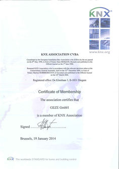
KNX Association Membership Certificate
(PDF | 160 KB)
User manual MBZ 300 configuration software …
OK OK ! OK ! OK OK ! OK ! OK ! OK ! MBZ300 MBZ300 MBZ300 MBZ300 MBZ300 OK ! MBZ300 MBZ300 OK ! MBZ300 MBZ300 USB ! MBZ300 PM PM CM DM DM DM DM SM DM DM Reset Reset MBZ 300 DE User manual Configuration Software Program for configuring RWA systems comprising components from the MBZ 300 series made by GEZE GmbH Software version … MBZ 300 Configuration Software Table of contents … About this document … Key to symbols … 2 System requirements … 3 General information … … .1 … .2 … .3 … .1 … .2 … .3 … .4 … .1 … .2 … .3 … .4 … .5 … .6 … Software installation … Licence levels … View licence . … Basic licence (partner level) … All licence (exclusively GEZE internal) … Authorisation (licensing) … Reading out the activation code (with control unit connected) … Reading out the activation code (alternative without control unit connected) … Requesting licence key . … Entering a licence key … Notes on the software … What happens after the system has been connected via USB … Status bar … Navigation bar … Menu functions … „Buttons“ on the interface … 10 EMU (emulator) … 11 Firmware update … 12 … Procedure for configuration of a control unit … 13 … Preparation of an individual control unit … 13 Several control units networked via CAN … 13 … Control system … 14 … RealTime_Log - control unit … 14 … PM - Power module … 15 … .1 … Purpose … 15 Electrical properties … 15 Status - PM … 15 PM target value table … 15 Properties – PM … 16 … CM - Control module … 18 … .1 … Purpose … 18 Electrical properties … 18 Status - CM … 18 Target value table … 18 Properties – CM … 19 Configuration possibilities (Partner level) … 19 … .1 … .2 … .3 … .4 … .5 … .6 … .7 … .8 … .9 … .10 … Vent switch function … 19 Automatic step control … 20 Emergency-close … 20 RWA button … 20 Smoke detector line … 20 Smoke detector line … 20 Reset key button … 20 CIE function … 20 Messaging relay … 21 LEDs … 21 System properties – CM … 21 MBZ 300 Configuration Software … .1 … .2 … .3 … .4 System … 21 Maintenance … 22 Operating parameters … 22 CAN parameters … 23 … DM - Drive module … 24 … .1 … .2 … .1 … .2 … .3 … .4 … .5 … .6 … .7 … .8 Purpose … 24 Electrical properties … 24 Status - DM … 24 Target value table DM … 24 Properties – DM … 25 Configuration possibilities … 25 Vent switch function … 25 Automatic step control … 26 Operating mode … 26 Emergency-open for wind directions (for SHEV according to EN 12101-2) … 26 Delays … 27 Movement time mode … 27 LEDs … 27 Status contacts … 28 … DME drive module - extended version … 30 … Purpose … 30 Electrical properties … 30 Status - DME … 30 Properties - DME and configuration possibilities . … 30 10 SM Sensor module … 31 … Purpose … 31 … Electrical properties … 31 … Status - SM … 31 … .1 Target value table SM … 31 … Properties – SM … 32 … Configuration possibilities … 32 … .1 Vent switch function … 32 … .2 Automatic step control … 33 … .3 Emergency-close … 33 … .4 RWA button … 33 … .5 Smoke detector line … 33 … .6 Smoke detector line … 33 … .7 Reset button … 33 … .8 CIE function … 33 … .9 Messaging relay … 34 … .10 LEDs … 34 11 WM - Weather module … 35 … .1 … .2 … .3 Purpose … 35 Electrical properties … 35 Status – WM … 35 Properties – WM … 35 Configuration possibilities … 36 Configuration … 36 Wind speed (for ventilation) … 36 Delay values (for ventilation) … 36 12 ERM relay module … 37 … .1 Purpose … 37 Electrical properties … 37 Status – ERM … 37 Target value table ERM … 37 … … MBZ 300 Configuration Software … .1 … .2 … .3 … .4 … .5 Properties – ERM … 38 Configuration possibilities … 38 General relay configuration . … 38 Relay configuration collective fault … 38 Alarm relay configuration (smoke zones) … 39 Signalling ventilation signals (venting groups) … 40 Signalling of weather groups … 40 13 Smoke zones … 40 … .1 … .2 … .3 … .4 … .5 … .6 Smoke zones … 41 Smoke zone details … 41 Independent detector lines … 42 Drive line faults … 42 Drive lines … 42 Smoke zone options … 42 Direction of travel … 42 Description … 42 14 Venting groups … 43 … .1 … .2 … .3 … .4 Venting groups … 44 Details of venting group … 44 Venting lines … 44 Drive lines … 44 Venting group options … 44 Description … 45 15 Weather groups … 45 … .1 … .2 … .3 … .4 Weather groups … 45 Weather group details … 45 Weather module inputs … 46 Drive lines … 46 Weather group options … 47 Description … 47 16 Higher-order smoke zones / venting groups / weather groups … 47 17 General information … 47 … Settings by software and VdS … 48 Cabling: Several smoke zones, networking and inter-control unit functions … 48 18 Testing the system … 48 19 FAQs … 48 … .1 … .2 … .3 … Sequence for commissioning and configuration by software … 49 What to do if...? … 49 The USB port driver is missing after installation … 49 The control unit is not shown correctly in the software (modules missing etc.) … 49 The software cannot be started completely. / The software „crashes“ during loading of the control unit … 49 Does the module sequence matter? … 49 Trouble shooting where several control units are in one CAN network … 49 How long are the motor follow-up times of the MBZ 300? … 49 20 Meaning of the log entries … 50 MBZ 300 Configuration Software … About this document About this document This user manual describes the the operation of the GEZE-MBZ 300 Configuration Software. … Key to symbols Warning In these instructions, warnings are used to warn against material damage and injuries. XX Always read and observe these warnings. XX Follow all instructions marked with the warning symbol and the word WARNING. Warning symbol Warning DANGER Meaning Danger for people. Non-observance can result in death or serious injuries. Further symbols used in these instructions Important information and technical notes are emphasised to illustrate the correct operation. Symbol Meaning means “Important note“ means “Additional information” XX … Symbol for a user action. Here you have to take an action. XX Observe the sequence if there are several action steps. System requirements The program can be installed on a computer with at least the following properties: CPU Operating system Memory Hard drive space Drive Graphic card / monitor Accessories Other requirements Recommended processor: … GHz or faster. If the processor is slower, at least a version with MMX is required. Microsoft Windows 2000 Server with Service Pack (SP) … or higher; Windows 2000 Professional Edition with SP … or higher; Windows XP with SP … or higher; Windows Server 2003 Standard Edition, Enterprise Edition, or Datacenter Edition with SP … or higher; Windows Small Business Server 2003 with SP … or higher, Windows Vista, Windows Server 2008, Windows 7. 512 MB RAM or more; … GB or more is recommended, at least 100 MB free RAM is required. At least 100 MB free hard drive space is required. At least … drive with a "C" partition is required Super VGA (1.024x768) or higher Microsoft mouse or compatible .NET … Runtime and the Visual C 2008 redistribution package. These packages are installed automatically by the installer package if they are not already in the system. … General information … General information … Software installation MBZ 300 Configuration Software After MBZ 300 software training you are registered in the user list. You then receive the software and licence via the GEZE customer portal. Please make sure you always work with the latest software. Please go to the GEZE customer portal: www.geze-partnerlogin.de Please install the software on a laptop which is used to commission the MBZ 300: àà You need administrator rights for installation àà Install the program in a file with writing rights for the user àà Make sure that the driver is also installed. (If this is not done automatically, the driver can be installed later from the directory „...\Programme\GEZE\MBZ300\Driver“ when an MBZ 300 control unit is installed.) … Licence levels The program can be cleared on different user levels by means of an authorisation system. Pre-condition for licensing is the acceptance of a licence contract with GEZE GmbH. … .1 View licence This level does not have to be cleared. After installation the software is automatically in the view level. The following possibilities are available: àà Display of system or module status àà Display of the log entries àà Setting of the charging current on the basis of the battery capacity àà When a weather module is installed: Setting of the type of peripherals connected and selection of wind speed àà Setting of the system time … .2 Basic licence (partner level) This level must be licensed. The following additional possibilities are then available: àà Modification of various module properties (see chapters on the various modules) àà Configuration of venting groups àà Activation of deluxe ventilation properties àà All module properties can be configured. àà Creation / configuration of smoke zones àà Configuration of extended networking of several MBZ300 via CAN àà Firmware update of individual modules àà Resetting to factory setting àà Password protection … .3 All licence (exclusively GEZE internal) This level must be licensed. The following additional possibilities are then available: àà Smoke detector reset period àà Smoke detector recovery period àà Delete system log. … Authorisation (licensing) … .1 Reading out the activation code (with control unit connected) First, the program must be started with the system connected (the MBZ300 must be connected to the computer to be licensed via USB). In the menu bar, click „File“ and then „Authorisation“. … MBZ 300 Configuration Software General information The following appears: … .2 Reading out the activation code (alternative without control unit connected) In the Windows start menu there is a shortcut to an external authorisation tool which can be used for authorisation without starting the program and connected to the control unit. Path for pre-installed software installation: START -> All programs -> GEZE -> MBZ 300 -> Authorisation Here, the activation code for a new licence can be read out. In addition, if an older program version was licensed this tool can transmit the existing PC „licence key“ to newly installed software by clicking the „Authorisation“ button. … .3 Requesting licence key Please go to the GEZE customer portal as a registered software user: www.geze-partnerlogin.de There, you can enter the activation code and request the key under „Authorisation“. It can be marked using the mouse, for example, copied to the clipboard using <strg>+<c> and then pasted using <strg>+<v>. Your contact responsible will send you the suitable licence key by email as soon as possible. If you have any questions, please contact MBZ300@geze.com. … .4 Entering a licence key If the authorisation window has been closed in the meantime, request it again as described above. Enter the licence key under „Licence key“. After you have clicked „Authorisation“ the extended functionality will be available. … Notes on the software Always use the latest configuration software together with the latest firmware! Update the firmware as required. Please note the two different program versions: àà „Individual control unit“ àà „Networked control unit“ (see „Firmware update“ and „Procedure for configuration of a control unit“) … General information … .1 MBZ 300 Configuration Software What happens after the system has been connected via USB As soon as the system has been connected to the PC, the settings and the current system configuration are read out. Depending on the size of the system, this procedure can take a few seconds. The software is ready when the info-area of the main window (bottom left) displays „Startup OK“: Please always operate the laptop on battery power to ensure the electrical isolation between the mains of the control unit and the power supply of the laptop. The program has to be terminated before the USB connection cable between the PC and MBZ300 is removed. … .2 Status bar In the status bar (info-area of the main window) at the bottom left you can see whether the control unit is ready and whether the configuration has been successfully saved to the control unit, for example. … .3 Navigation bar All the modules connected in the system are displayed in a tree view, and from the basic licence onwards the groups are listed: The properties of each module can be reached by clicking the symbol on the left of the respective module. … MBZ 300 Configuration Software … .4 General information Menu functions A wide range of different software functions can be executed via the menu in the header. Navigation is by left mouse click, analogue to familiar programs. File Load configuration... A saved configuration (*.EMB) is loaded to the software interface. It is not yet written into the system. XX Please check the settings after loading. XX The following settings are not saved in the file and must be adapted manually àà PM: àà Size of the battery àà Number of PMEs àà WM: àà Sensors àà Wind thresholds àà CM: àà Maintenance time àà Time àà Password See „System configuration“ for how to write the configuration into the system The current configuration is saved in a file (*.EMB) on the PC. Like „Save configuration...“ but under a new file name. see „Authorisation“ Protect the system by means of a password. Page set-up. Documentation of the system acceptance protocol/check list. XX Save configuration... Save configuration as ... Authorisation... Set Password of the selected device... Printer settings... Printer preview selected device... Printer preview of all devices... Print the configuration of the selected device... Print the configuration of all devices... Generate a PDF of the selected device configuration... Generate a PDF containing all device configurations... Exit Note: In order to get all current status entries in the PDF as well, click in all modules (status page) before generation / printing to ensure the current status displays are requested. Terminates the program … General information MBZ 300 Configuration Software System configuration Load default configuration of the directly The system configuration is reset to factory settings. The self-teaching connected control unit... function is re-activated. Refer also to „ „Buttons“ on the interface“ Note: All the settings are lost! Write configuration permanently to the devices Load configuration from the device The configuration in the software interface is transmitted to the system. Refer also to „ „Buttons“ on the interface“ Reads the existing configuration out of the system and displays it in the software interface. If a configuration in the software interface is not saved it is lost. Reboot the directly connected device... Reboots the connected system. It is necessary to reboot the system when all the required changes have been written into the system and a check on system behaviour is to be made. = equivalent to: switching the control unit voltage-free for at least 30 seconds (without rechargeable battery). … .5 „Buttons“ on the interface As an alternative to items from the header menu, some functions are available as buttons. The functions of the button are described below. „Clear“ The system configuration is reset to factory settings. Refer also to „System configuration“. Note: All the settings are lost! „Save to CM“ The configuration in the software interface is transmitted to the system. Refer also to „System configuration“. „Undo“ Changes to the configuration in the software interface are reversed. Note: This only affects the current view on the PC, not the control unit. For this, the configuration has to be re-transmitted to the control unit. Whether or not a property can be modified depends on the user level. 10 MBZ 300 Configuration Software … .6 General information EMU (emulator) The emulator is used to simulate system set-up when the PC is no longer connected to an MBZ 300 control unit. To simulate the system set-up, the various modules are added to a list in descending order. The modules can be moved in the list by drag-and-drop. Then the system set-up is loaded to the configuration program, where the settings can be made. PM, CM, DM, SM, DME, WM, ERM Adds the corresponding module to the list. System separation Allows a new control unit to be started in the list in order to map several control units connected via CAN-bus. (This function only becomes effective when the "Networked control units" program version is used.) Delete selection Delete all Deletes the module selected in the list Deletes all the modules from the list Load into App Def. Cfg. Loads the list as system set-up into the configuration program. When configuration has been completed it can be saved (*.EMB) in order to be exported to an actually existing control unit locally at a later date. The configuration file of an actually existing system can also be loaded into an identical, emulated system. The configuration can only be loaded to an identical control unit (same module sequence). The set-up must be known. Tip: Always save the *.PDF file in addition to the configuration file (*.EMB). XX Please check the settings on the real control unit! The following settings are not saved in the *.EMB file and must be adapted manually: àà PM: Battery size and number of PMEs àà WM: Sensors and wind thresholds àà CM: Maintenance time and time àà Password 11 General information … MBZ 300 Configuration Software Firmware update Carry out the firmware update using the „Update“ program. You will find the program in the Start menu. Please proceed as follows: XX Connect the control unit via USB XX Start Update program. Path for pre-installed software installation: START -> All programs -> GEZE -> MBZ 300 -> Update -> Update The Update program contains the following: àà Intermediate saving of the configuration àà Updating of all firmware statuses of the modules installed XX 12 àà Loading of the configuration which has been saved intermediately Starting of the software „Individual control unit“. The following settings are not saved intermediately and must be adapted manually: àà PM: Battery size and number of PMEs àà WM: Sensors and wind thresholds àà CM: Maintenance time and time àà Password MBZ 300 Configuration Software … Procedure for configuration of a control unit Procedure for configuration of a control unit Please note the following steps when commissioning or modifying an MBZ 300: … Preparation of an individual control unit [1] Ensure the system is voltage-free (no 230V connection, no battery) [2] Insert further modules if appropriate XX [3] Check wiring between the modules àà Power supply àà Bus cable (NEVER connect or disconnect when the control unit is switched on!) àà Ensure that the cables are fitted correctly. àà Connect drives, push buttons etc. (can also be done later) àà Make sure that all line monitoring devices are connected properly XX [4] Activate the 230V supply XX [5] Connect the rechargeable battery XX [6] Keep the reset push button on the CM pressed for 20s (until all modules are flashing - not longer!). This ensures the modules are addressed correctly. This process is essential when the hardware (modules and order) has been changed. XX [7] Connect USB cable to CM and connect to the laptop. XX [8] Start the software „Individual control unit“ (please make sure you always use the current version (see „Software installation“). XX [9] Check the firmware version of the control unit to make sure it is up-to-date. XX [10] Carry out firmware update if necessary (see „Firmware update“) XX [11] Load the default settings (see „System configuration“) Standard groups (alarm / ventilation / weather groups) are formed along module settings through the selflearning function (connection of modules) or default loading. Caution: all previous settings are deleted! XX [12] Adapt battery size and number of PMEs (see „Battery settings“). XX [13] Set the individual configuration: à If new modules are added or the order is changed, the settings must be adjusted manually directly in the software. à If the hardware has not changed, you can load an already saved *.EMB-file. Prerequisite is a suitable (same) hardware configuration! Please check the settings (see Section … .4) and go to the next step. XX [14] Transmit to the control unit. XX [15] Reboot the directly connected control unit. XX [16] Check settings. XX [17] Test functions (please note interactions with GLT, BMA, relaying!). XX [18] Save central configuration as *.EMB and *.PDF and archive for the project. XX [19] In the control unit, note that the configuration has been adapted by software (user, date and rough description – print out PDF and enclose if appropriate). XX [20] Terminate software, then remove USB cable. XX XX … Several control units networked via CAN (see „CAN parameters“) The procedure is in addition to / instead of the above-described points as follows: Set up the USB connection to each individual control unit and start the software „Individual control unit“ every time. XX [12a]: For every individual control unit with CM CAN parameters set the address and the number of control units. XX Transmit to the control unit XX Reboot the directly connected control unit XX It is advisable to mark the control units according to their addresses XX [12b]: At this point at the latest, make sure that the CAN cables incl. terminator jumper are correctly connected between the control units XX Establish a USB connection to any control unit XX Open the „Networked control units“ software XX zu [13]: Set the configurations and particularly comprehensive functions now and transmit to the control units. XX zu [18]: Save the configuration file as *.EMB (several files) and *.PDF. 13 Control system … MBZ 300 Configuration Software Control system The individual setting possibilities for the various modules are described below. The standard value is always in bold type. … RealTime_Log - control unit The program displays the entries in the „RealTime_Log“ memory. This lists events which have had at least alarm or error status. Various selection possibilities can be used to set which events and messages are to be recorded. The setting does not represent a filter of the view, rather it specifies what is actually to be saved. Granularity: Fine (everything) All events are saved e.g. including ventilation control Information Alarm Error All messages are saved Alarm and error messages are saved Error messages are saved Note: The granularity settings must be written into the system for the changes to take effect Read all available entries Empty textbox Save textbox content... Empty the devices log All the messages available for the control unit are read. Caution: This can take a very long time! Only deletes the display on the software interface. Saves the contents of the fault memory in a file. (.TXT) Deletes the fault memory of the control unit. The log is a circular buffer (the oldest data are overwritten) with sufficient capacity (depending on granularity). Tip: Use the log memory for trouble shooting and for functional test (granularity „Fine“). 14 MBZ 300 Configuration Software … PM - Power module … Purpose PM - Power module àà Provision of a non-interrupted power supply. àà Battery charging. àà Provision of secondary voltages. … Electrical properties OK ! Possible battery sizes … .. 38 Ah, 24 V Battery types Lead MBZ300 PM Load bearing capacity voltage outputs 0,5 A, SELV … Status - PM The current status can be compared with the target value table shown below to evaluate the condition … .1 PM target value table Inputs Battery voltage Device voltage Current control voltage Current battery charge Voltage power supply … Voltage power supply … Voltage power supply … Temperature Minimum value Standard value approx. 24 V (depending on … V (depending on the the battery charge state) temperature, if configured this way) 23 V Mains operation: as power supply voltage Battery operation: as battery voltage Approx. … mA/module depending on system version Between … A .. … A depending on the battery capacity configured 23,5 V 26 V 23,5 V *) 26 V *) 23,5 V *) 26 V *) … °C 25 °C Maximum value … V (depending on the temperature, if configured this way) 28 V 0,5 A 1,8 A 28 V 28 V *) 28 V *) 40 °C *) if the corresponding number of PMEs has been configured, otherwise display is „ … V“ 15 PM - Power module … MBZ 300 Configuration Software Properties – PM Akkuüberwachung [•] Fault indication Fault indication is outputted via the malfunction LED or e.g. via the signal relay with corresponding parameter settings. [] Battery control deactivated No reaction in the event of a malfunction. [] Fault indication and windows close A fault indication is outputted and all drive modules are actuated to CLOSE. [] Fault indication and windows open A fault indication is outputted and all drive modules are actuated to OPEN. [] Deep discharge protection In battery operation, the control unit does not operate until the rechargeable battery is completely discharged (deep discharge), it is switched off before this point in order to protect the rechargeable battery (this deep discharge protection triggers at around … V) e.g. if the power failure can last for longer than 72 h. Note: Fault display on the PM is still active. Desired charging characteristic [•] Temperature-guided [] Constant The charging voltage is adapted depending on the temperature. Should always be used. The charging voltage is independent of the ambient temperature. Mains power failure [•] [] [] Energy-saving mode Close all windows Allow venting Ventilation signals are suppressed, weather sensors are not evaluated All drive modules are actuated to CLOSE in the event of a power failure. Ventilation is allowed. The back-up time is shortened by ventilation movements in battery operation. Battery settings Number of connected PMEs 0..2 (Standard: 0) Adaptation of the number of PMEs if any changes have been made to the power supply If the system has been extended by further power supplies, a corresponding number of PME modules have also been added. This number must be configured here (range 0..2) so that fault evaluation works correctly. 16 MBZ 300 Configuration Software Battery type: PM - Power module … Ah … Ah 10 Ah 12 Ah 17 Ah 24 Ah 38 Ah The corresponding battery type must be set After the default values have been loaded, this setting must always be checked and adapted if necessary! CAUTION If the battery type is set incorrectly this can lead to excessively high charging current. Excessively high charging current can damage the rechargeable battery. The rechargeable battery will become very hot: Risk of explosion! The parameters must always be checked following a software update on a control unit. 17 CM - Control module MBZ 300 Configuration Software … CM - Control module … Purpose àà àà àà àà àà àà àà àà … Control and operation of the complete system. The configuration settings of the control unit are mainly saved in the CM. Evaluation/monitoring of manual detectors. Evaluation/monitoring of automatic fire alarms or external alarm contacts. Evaluation of ventilation signals. Provision of a potential-free contact (signal relay). Connection possibility with a PC via USB Connection of several MBZ300 systems via CAN (CAN additional module necessary) Electrical properties OK ! Alarm voltage 24 V DC Input switching voltage 24 V DC Load bearing capacity signal relay 0,5 A, SELV MBZ300 USB CM Reset … Status - CM The current status can be compared with the target value table shown below to evaluate the condition. … .1 Target value table Inputs Control voltage RWA Open-Button Power Smoke detector line … Power Smoke detector line … Power RWA Close-Button Power Push button status 18 Minimum value Standard value Maximum value 22 V 25,3 V 28 V 900 µA (standby) 1250 µA (standby) 3000 µA (standby) 1000 µA (standby) 2550 µA (standby) 6000 µA (standby) 1000 µA (standby) 2550 µA (standby) 6000 µA (standby) 1000 µA (standby) 1250 µA (standby) 3000 µA (standby) Depending on the switched status NA (not actuated), OPEN, CLOSE or STOP MBZ 300 Configuration Software … CM - Control module Properties – CM Ventilation RWA signals In the standard configuration the CM forms the first smoke zone. All the following DMs (up to the next SM) are assigned to this smoke zone. Other smoke zone assignment (see „Smoke zones“). … Configuration possibilities … .1 Vent switch function (Partner level) In the standard configuration the push button input of the control module in the first venting group is linked with all drive modules in the system. This venting group has a higher priority than the push buttons connected directly to the drive modules (= central push button for the whole control unit). Other venting group assignment (see „Venting groups“). Function setting Behaviour with button OPEN pressed [] Biased-off Note: Always select OPEN and / or CLOSE in addition. Without this definition the push button continues to be in self-locking mode. [] open close If "CLOSE" is not set to biased-off, the DMs switch to the "close" direction of travel permanently. The DMs switch to "close" as long as the button is pressed. If the button is released, the DMs switch off again. In biased-off direction: Release the push button [] The DMs switch to "open" as long as the button is pressed. If the button is released, the DMs switch off again. If "OPEN" is not set to biasedoff, the DMs switch to the "open" direction of travel permanently. Modules switch permanently to "open" direction of travel. Modules switch permanently to „open“ direction of travel. Pressing the button again switches the lines off again (stop) Modules switch permanently to „open“ direction of travel. Stop = Press both push buttons at the same time Modules switch permanently to "close" direction of travel. Modules switch permanently to „close“ direction of travel. Stop = Press both push buttons at the same time Modules switch permanently to „close“ direction of travel. Pressing the button again switches the lines off again (stop). Press both push buttons at the same time If both directions are activated: [•] Self-locking [] Start/stop open push button [] Start/stop close push button Behaviour with button CLOSE pressed Stop by If only one is active, the other is in self-locking mode STOP = both push buttons at the same time Stop = Press the same button again Note: If the function „stop through same push button“ is desired: Check OPEN and CLOSE so that the ventilation push button function makes sense. „Permanently“ means the set „drive line switch-off time“ at maximum. 19 CM - Control module … .2 MBZ 300 Configuration Software Automatic step control [] Use mechanism Interval time: When this option is activated the drives are only actuated in the „OPEN“ direction for the time step set. This function must be combined with the ventilation push button function „self-locking“. This has no influence on the RWA function. … .. 120 s (Standard: … s) Movement interval of the interval time. Pressing the push button again during movement increases the overall interval time by the respectively set interval time. (Example: First time push button pressed = … s, second time = 10 s, third time = 15 s etc.) … .3 Emergency-close (Concerns the green push button „CLOSE/RESET“ in the connected RWA button) [•] Emergency-close [] Emergency-close and detector line reset When the emergency-close push button of the manual detector is actuated, all DMs of the smoke zone are switched to "close" and the alarm status in the control unit is reset. If a smoke detector reset should be necessary, this must be carried out directly at the module via the "RESET" push button. When the emergency-close push button of the manual detector is actuated, all DMs of the smoke zone are switched to "close" and the alarm status in the control unit is reset. The smoke detectors are also reset. „Emergency-close“ always has the effect of triggering a „CLOSE“ movement and (partly) resets the alarm status, no matter whether alarm signals (e.g. fire alarm system) are pending or not. All pending alarm signals must be removed for complete alarm reset. … .4 RWA button [] … .5 Disable error detection Error detection (line monitoring) of the smoke detector line … is thus deactivated. Line break and short-circuit are no longer recognised! This means setting a terminating resistance is superfluous. Smoke detector line … [] … .7 Error detection (line monitoring) of the RWA button line is thus deactivated. Line break and short-circuit are no longer recognised! This means setting a terminating resistance is superfluous. Smoke detector line … [] … .6 Disable error detection Disable error detection Error detection (line monitoring) of smoke detector line … can be deactivated, line break and short-circuit are no longer recognised! This means setting a terminating resistance is superfluous. Reset key button (Concerns the reset key button directly on the CM module) [] Reset alarm status As standard, brief confirmation of the key button only resets the smoke detector of the smoke detector lines of the smoke zone (smoke detector reset see „Operating parameters (GEZE internal All Licence)“). When the option is activated, the alarm is also reset in the assigned smoke zones and all the drive modules are actuated to „close“. àà Please check how meaningful this function is if the module detector lines are used for different smoke zones. àà If „Reset alarm status“ is activated, the alarm status is only reset and the drive modules actuated to „close“ when all pending alarm signals have been removed. … .8 20 CIE function Automatic remote resetting of the alarm status via fire alarm system. [] Smoke detector line … [] Smoke detector line … When this option is activated, opening the fire alarm system status contact to smoke detector line … will automatically reset the control unit. When this option is activated, opening the fire alarm system status contact to smoke detector line … will automatically reset the control unit. MBZ 300 Configuration Software CM - Control module àà The fire alarm system function covers resetting the alarm status and CLOSING the drives. àà If „Emergency-close and detector line reset“ is activated in combination with the fire alarm function, the smoke detector lines are switched voltage-free for the time set under „Smoke detector reset period“ (see CM „Operating parameters“) when the fire alarm signal is no longer received. … .9 Messaging relay Selection of the message which leads to the messaging relay switching. Trigger in case of: Never Fault within the group General group alarm No reaction. Or alternative function (see CM „Operating parameters“: Setting „Collective fault“) The messaging relay switches when there is a fault within the group (concerns faults on modules which are assigned to the smoke zones of the CM). The messaging relay switches when there is an alarm within the group (smoke zone). Note: Changeover contact NC/NO is inverted! Delay for messaging relay: Time-limited signal 0..0 sec 0..0 sec Currently disabled. Currently disabled. … .10 LEDs The function of the LEDs on the RWA button are shown here. If „alternative function“ is selected, the display of the LEDs depends on the special system functions set. … System properties – CM The system settings are made here. … .1 System Time: synchronise Setting the system time. The system time can be compared with the time on the PC connected by pressing the „synchronise“ button. Please make sure that the PC time is correct. The system time is used for the time stamp for messages in the RealTime log. 21 CM - Control module … .2 MBZ 300 Configuration Software Maintenance Next maintenance The date for the next routine system maintenance check can be set here using a date selection list. Signalling: [•] Note: There is no date set as standard. [] [] [] [] CM fault LED flashing Any maintenance due is signalled by the fault LED flashing on the CM. CM fault LED flashes and Maintenance due is signalled by the fault LED flashing on the messaging relay is set CM and by the messaging relay being switched. Ventilation open blocked on When maintenance is due, ventilation movement in the all DMs OPEN direction is blocked on all DMs. Flashing + ventilation open Maintenance due is signalled by the fault LED on the CM flasblocked hing and ventilation movement in the OPEN direction being blocked on all DMs. Flashing + relay + ventilation Maintenance due is signalled by the fault LED on the CM flasopen blocked hing, by the messaging relay being switched and ventilation movement in the OPEN direction being blocked on all DMs. Note: GEZE recommends variant … or … [•] … .3 Suppress message The maintenance message can be suppressed completely here. Operating parameters (GEZE internal All Licence) Smoke detector reset period Smoke detector recover time after SD reset 0..60 s (Standard: … s) 0..1000 ms (Standard: 500 ms) Smoke detectors are reset by switching off the supply voltage to the detector for the period set here. The detector line evaluation is deactivated for the time given here following reset of a smoke detector line. During the smoke detector reset no detector line evaluation takes place, including on the RWA button lines. [] [] [] [] [] no post cycle control Post cycle control (= VdS post-triggering) is suppressed in the event of an alarm. Alarm triggering in case of RWA line An alarm is triggered in the event of a line break or short-circuit on a error RWA button line. Alarm triggering in case of smoke An alarm is triggered in the event of a line break or short-circuit on detector line … line error smoke detector line 1. Alarm triggering in case of smoke An alarm is triggered in the event of a line break or short-circuit on detector line … line error smoke detector line 2. Common fault of the network system The system-wide issue of faults is activated. Faults are shown on all RWA buttons in the network system (all control unit modules and control units networked via CAN). Note: àà When the collective fault is activated, the LED setting „Fault“ in the CM and SM properties is set to „Alternative functions“ and the drop-down menu is deactivated. Caution: àà When the collective fault is subsequently deactivated the function of the LED must be restored manually. (see „LEDs“ in CM and SM) [] Use relay for signalling too The messaging relays of all CM and SM are switched in the event of collective fault. Note: àà Changeover contact NC/NO is inverted! àà When the relays are activated, the setting „Trigger messaging relay for:“ in CM and SM is set to „Never“ and the dropdown menu is deactivated. Caution: àà When „Use relay for signalling too“ is subsequently deactivated, the settings must be restored manually. 22 MBZ 300 Configuration Software CM - Control module àà With the MBZ 300, post cycle control means CLOSE briefly every … min and then OPEN signal again for a total of 30 min. All GEZE window drives have been designed for this post cycle control. àà The collective fault is also transmitted in the CAN-bus network. Display can be delayed by several minutes in the case of triggering and particularly resetting / eliminated the fault via the CAN-bus. … .4 CAN parameters In the case of control units networked via CAN-bus, an individual address must be entered here for each control unit. The setting remains „0 of 0“ for some control units. CAN address: … .. 30 (Standard: 0) from … .. 30 (Standard: 0) (starting with 1) is increased by … for every control unit so that each control unit is assigned an unambiguous sequential number in the system. Number of all control units in the network. (Refer also to „Several control units networked via CAN“) The CAN-bus is an MBZ 300-internal bus and is exclusively used for the networking of several control units. 23 DM - Drive module … DM - Drive module … Purpose MBZ 300 Configuration Software àà Actuation of 24V drives for RWA and/or ventilation purposes. àà Evaluation of ventilation signals and status contacts. àà Monitoring of the drive cable (see MBZ 300 installation instructions). … Electrical properties Max. drive current 10 A Input switching voltage: 24 V DC OK ! MBZ300 DM … Status - DM The current status can be compared with the target value table shown below to evaluate the condition. … .1 Target value table DM Inputs 24V supply + 24 V supply Control voltage Clamp … drive line Clamp … drive line Drive monitoring Push button status Drive end position Number of cycles 24 Minimum value Standard value Maximum value 23,5 V 26 V 28 V … V (without load) … V (without load) … V (with load) 21 V 25,3 V 28 V OPEN or stopped when switched: … .. … V (without load), max. … . V (with load). CLOSE when switched: … V .. 28 V OPEN when switched: … V .. 28 V CLOSE or stopped when switched: … .. … V (without load), max. … V (with load) 0,8 V 1V 3V Depending on the switched status NA (not actuated), L_L_OPEN, L_L_CLOSE or L_L_ STOP Concerns the signal inputs: Depending on the switched status NA (not actuated), E_A_ OPEN (status contact 1) or E_A_CLOSE (status contact 2) Counts how often the line has been switched open and closed MBZ 300 Configuration Software DM - Drive module … .2 Properties – DM … Configuration possibilities … .1 Vent switch function (Partner level) In the standard configuration the push button input of the drive module in a venting group is linked with this drive module itself. Other venting group assignment (see „Venting groups“). Function setting Behaviour with button OPEN pressed [] Note: Always select OPEN and / or CLOSE in addition. Without this definition the push button continues to be in self-locking mode. Dead-man [] [•] Behaviour with button CLOSE Stop by pressed open The DMs switch to "open" If "CLOSE" is not set to In biased-off direction: Reas long as the button is biased-off, the DMs switch to lease the push button pressed. If the button is the "close" direction of travel released, the DMs switch off permanently. again. [] close If "OPEN" is not set to The DMs switch to "close" as If only one is active, the other biased-off, the DMs switch long as the button is pressed. is in self-locking mode STOP to the "open" direction of If the button is released, the = both push buttons at the same time travel permanently. DMs switch off again. Self-locking Modules switch permaModules switch permanently Press both push buttons at nently to "open" direction to "close" direction of travel. the same time of travel. [] Start/stop Modules switch permanent- Modules switch permanently If both directions are actiopen push ly to „open“ direction of to „close“ direction of travel. vated: button travel. Pressing the button Stop = Press both push butagain switches the lines off tons at the same time Stop = Press the same button again (stop) again [] Start/stop Modules switch permanent- Modules switch permanently close push ly to „open“ direction of to „close“ direction of travel. button travel. Pressing the button again Stop = Press both push but- switches the lines off again tons at the same time (stop). Note: If the function „stop through same push button“ is desired: Check OPEN and CLOSE so that the ventilation push button function makes sense. „Permanently“ means the set „drive line switch-off time“ at maximum. 25 DM - Drive module … .2 MBZ 300 Configuration Software Automatic step control [] Interval time Use mechanism When this option is activated the drives are actuated in the „OPEN“ direction for the time step set. This function must be combined with the ventilation push button function „self-locking“. This has no influence on the RWA function. 0..120 s Movement interval of the interval time. (Standard: … s) Pressing the push button again during movement increases the overall interval time by the respectively set interval time. (Example: First time push button pressed = … s, second time = 10 s, third time = 15 s etc.) … .3 Operating mode [•] Standard motor [] Magnetic clamp operation This mode is designated for standard 24V drives on ventilation flaps and windows. The change in direction is achieved by reversing the polarity of the supply voltage. The drive lines are only supplied (for the duration of the drive line switch-off time) when an OPEN or CLOSE signal is pending. In the event of an alarm, the post cycle control is also active (see CM „Operating parameters“). This mode is designated for the connection of magnetic clamps. The module only reacts to alarm commands. The LED „Window OPEN“ on the module and on any vent switch (without function!) connected lights up red in idling state. The LED indicator „Window OPEN“ on the fire button is not active. Note: àà In magnetic clamp mode the maximum current must be taken into account (30% of the power supply). The battery movement time must be calculated separately. When current is permanently tapped, a back-up time of 72 h can no longer be achieved. Mixed designs (drives and magnetic clamps) require particular consideration. àà This setting requires the alarm direction of travel „Emergency-open“. Important note: àà If a DM with magnetic clamp mode is connected to a control unit, the LED indicator „Window OPEN“ is not active on the fire buttons connected. We recommend using separate control units for standard drives and magnetic clamps. [] Idling state: Drive line actuated ("Open") Alarm state: Drive line off Pressure gas genera- This mode is designated for the connection of pressure gas generators. The module only tor mode reacts to alarm commands. Note: àà If „Impulse duration“ = … is set, the drive line remains on permanently in alarm state. Idling state: Alarm state: Impulse duration: [] … .4 Drive line off Drive line actuated ("Open") for the set "impulse duration" … .. 100 s (Standard: … s) … sec = permanent operation Restoring a switAfter a higher priority signal has dropped, the drive line is returned to the status of a ched status of lower pending. lower priority signal again. priority Example: A ventilation signal OPEN is pending due to a temperature sensor, the windows are open. A higher priority ventilation signal CLOSE transmitted by a weather station closes the windows. If the ventilation signal of the weather station drops further and the ventilation signal of the temperature sensor is still pending, the windows open again. Emergency-open for wind directions (for SHEV according to EN 12101-2) Specifies the evaluated wind directions for which the system actuates the drive line of the DM in the event of an alarm. [x] [x] [x] [x] [x] [x] [x] [x] 26 N NO O SO S SW W NW The wind direction is evaluated according to VdS 3122. In the event of an alarm and a wind direction during which the windows should not be opened, the windows close if they have been opened by ventilation. This function guarantees a wind direction dependent actuation of SHEVs (natural smoke and heat exhaust ventilators) in the event of an alarm according to EN 12101-2. MBZ 300 Configuration Software DM - Drive module This function is only possible when a weather module is available and the wind direction sensor (wind direction finder) is connected. (see „WM - Weather module“) … .5 Delays Start delay Changeover delay Drive line switch-off time 0..2,50 s (Standard: … s) Response time to a control command (for cascading of the DMs with several drives with high switch-on peak currents) 0..2,50 s (Standard: 0,10 s) 10..3600 s (Standard: 300 s) Voltage-free phase during changeover. Note: àà The switch-on delay serves to map delayed sequence control. Maximum operating period for a drive line following a switching command. This time applies for ventilation OPEN and CLOSE but not for an alarm. The drive line switch-off time for RESET-CLOSE cannot be set. Note: àà When in active movement time mode the drive line switch-off time should be set greater than the movement time. … .6 Movement time mode [] Movement time [] Movement time in OPEN direction: Venting duration Drives close after: The maximum ventilation stroke can be limited with this option activated („gap ventilation“). A „Ventilation open“ command activates the drive line in open direction. The line stops automatically after the set „opening time“. A further „Ventilation open“ command is then ignored. Operation can also be stopped during movement. A further open command then only activates the line for the residual time. The movement time is ignored in the alarm case. 0..6000 s (Standard: 60 s) … s – Drives are not actuated (line blocked) If „Venting duration“ ... „drives close after“ is activated, the ventilation line automatically switches to „close“ after the set time. 0..6000 min (Standard: … min) … min – Drives never close (permanently open) àà The movement time mode is only available in the operating mode „standard motor“. àà If „Movement time in OPEN direction“ has been activated, the drive line of the DM is initially automatically actuated to „close“ (initialisation). The ventilation „open“ commands are blocked for the double time so that the drives can move to „close“ in a defined manner. àà The movement time functions are inactive for alarm. After „reset close“ the ventilation commands are blocked for the double movement time again. … .7 LEDs The function of the LEDs on the RWA button are shown here. If „alternative function“ is selected, the display of the LEDs depends on the function of the status contacts. 27 DM - Drive module … .8 Status contacts The status contacts of DM and DME are not available in the PC software … . 28 MBZ 300 Configuration Software MBZ 300 Configuration Software DM - Drive module 29 DME drive module - extended version MBZ 300 Configuration Software … DME drive module - extended version … Purpose àà Actuation of 24V drives for RWA and/or ventilation purposes. àà Evaluation of ventilation signals and status contacts. àà Monitoring of the drive cable (see MBZ 300 installation instructions). … Electrical properties Max. drive current 20 A Input switching voltage: 24 V DC OK ! MBZ300 DME … Status - DME (see „Status - DM“) … Properties - DME and configuration possibilities (Partner level) Cf. DM: „Configuration possibilities“ 30 MBZ 300 Configuration Software 10 SM Sensor module SM Sensor module … Purpose àà àà àà àà Evaluation/monitoring of manual detectors. Evaluation/monitoring of automatic fire alarms or external alarm contacts. Evaluation of ventilation signals. Provision of a potential-free contact (signal relay). … Electrical properties OK Alarm voltage 24 V DC Input switching voltage 24 V DC Load bearing capacity signal relay 0,5 A, SELV MBZ300 SM Reset … Status - SM The current status can be compared with the target value table shown below to evaluate the condition. … .1 Target value table SM Inputs Control voltage RWA Open-Button Power Smoke detector line … Power Smoke detector line … Power RWA Close-Button Power Push button status Minimum value Standard value Maximum value 22 V 25,3 V 28 V 900 µA (standby) 1250 µA (standby) 3000 µA (standby) 1000 µA (standby) 2550 µA (standby) 6000 µA (standby) 1000 µA (standby) 2550 µA (standby) 6000 µA (standby) 1000 µA (standby) 1250 µA (standby) 3000 µA (standby) Depending on the switched status NA (not actuated), OPEN, CLOSE or STOP 31 SM Sensor module MBZ 300 Configuration Software … Properties – SM In the standard configuration the SM forms a new smoke zone. All the following DMs (up to the next SM) are assigned to this smoke zone. Other smoke zone assignment (see „Smoke zones“). … Configuration possibilities (Partner level) … .1 Vent switch function In the standard configuration the push button input of the sensor module in a venting group is linked with all the drive modules in this smoke zone. This venting group has a higher priority than the push buttons connected directly to the drive modules (= central push button for the smoke zone). Other venting group assignment (see „Venting groups“). Function setting Behaviour with button OPEN pressed [] Note: Always select OPEN and / or CLOSE in addition. Without this definition the push button continues to be in self-locking mode. Dead-man [] [•] Behaviour with button CLOSE Stop by pressed open The DMs switch to "open" If "CLOSE" is not set to In biased-off direction: Reas long as the button is biased-off, the DMs switch to lease the push button pressed. If the button is the "close" direction of travel released, the DMs switch off permanently. If only one is active, the other again. is in self-locking mode STOP [] close If "OPEN" is not set to The DMs switch to "close" as = both push buttons at the biased-off, the DMs switch long as the button is pressed. same time to the "open" direction of If the button is released, the travel permanently. DMs switch off again. Self-locking Modules switch permaModules switch permanently Press both push buttons at nently to "open" direction to "close" direction of travel. the same time of travel. [] Start/stop Modules switch permanent- Modules switch permanently If both directions are actiopen push ly to „open“ direction of to „close“ direction of travel. vated: button travel. Pressing the button Stop = Press both push butagain switches the lines off tons at the same time Stop = Press the same button again (stop). again [] Start/stop Modules switch permanent- Modules switch permanently close push ly to „open“ direction of to „close“ direction of travel. button travel. Pressing the button again Stop = Press both push but- switches the lines off again tons at the same time (stop). Note: If the function „stop through same push button“ is desired: Check OPEN and CLOSE so that the ventilation push button function makes sense. „Permanently“ means the set „drive line switch-off time“ at maximum 32 MBZ 300 Configuration Software SM Sensor module … .2 Automatic step control [] Use mechanism Interval time: … .. 120 s (Standard: … s) When this option is activated the drives are only actuated in the „OPEN“ direction for the time step set. This function must be combined with the ventilation push button function „self-locking“. This has no influence on the RWA function. Movement interval of the interval time. Pressing the push button again during movement increases the overall interval time by the respectively set interval time. (Example: First time push button pressed = … s, second time = 10 s, third time = 15 s etc.) … .3 Emergency-close (Concerns the green push button „CLOSE/RESET“ in the connected RWA button) [•] [] Emergency-close When the emergency-close push button of the manual detector is actuated, all DMs of the smoke zone are switched to „close“ and the alarm status in the control unit is reset. If a smoke detector reset should be necessary, this must be carried out directly at the module via the „RESET“ push button. Emergency-close and detector line When the emergency-close push button of the manual detector is acreset tuated, all DMs of the smoke zone are switched to „close“ and the alarm status in the control unit is reset. The smoke detectors are also reset. Note: „Emergency-close“ always has the effect of triggering a „CLOSE“ movement and (partly) resets the alarm status, no matter whether alarm signals (e.g. fire alarm system) are pending or not. All pending alarm signals must be removed for complete alarm reset. … .4 RWA button [] Error detection (line monitoring) of the RWA button line is thus deactivated. Line break and short-circuit are no longer recognised! This means setting a terminating resistance is superfluous. … .5 Smoke detector line … [] Disable error detection Error detection (line monitoring) of the smoke detector line … is thus deactivated. Line break and short-circuit are no longer recognised! This means setting a terminating resistance is superfluous. … .6 Smoke detector line … [] Disable error detection Error detection (line monitoring) of smoke detector line … can be deactivated, line break and short-circuit are no longer recognised! This means setting a terminating resistance is superfluous. … .7 Reset button (Concerns the reset key button directly on the SM module) [] Reset alarm status As standard, brief confirmation of the push button only resets the smoke detector of the smoke detector lines of the smoke zone (smoke detector reset -> see „Operating parameters“(GEZE internal All Licence)) . When the option is activated, the alarm is also reset in the assigned smoke zones and all the drive modules are actuated to „close“. àà Please check how meaningful this function is if the module detector lines are used for different smoke zones. àà If „Reset alarm status“ is activated, the alarm status is only reset when all pending alarm signals have been removed. … .8 CIE function Automatic remote resetting of the alarm status via fire alarm system. [] Smoke detector line … [] Smoke detector line … When this option is activated, opening the fire alarm system status contact to smoke detector line … will automatically reset the control unit. When this option is activated, opening the fire alarm system status contact to smoke detector line … will automatically reset the control unit. 33 SM Sensor module MBZ 300 Configuration Software àà The fire alarm system function covers resetting the alarm status and CLOSING the drives. àà If „Emergency-close and detector line reset“ is activated in combination with the fire alarm function, the smoke detector lines are switched voltage-free for the time set under „Smoke detector reset period“ (see „Operating parameters“) when the fire alarm signal is no longer received. … .9 Messaging relay Selection of the message which leads to the messaging relay switching. Trigger in case of: Never Fault within the group General group alarm No reaction. Or alternative function (see CM „Operating parameters“: Setting „Collective fault“) The messaging relay switches when there is a fault within the group (concerns faults on modules which are assigned to the smoke zones of the SM). The messaging relay switches when there is an alarm within the group (smoke zone). Note: Changeover contact NC/NO is inverted! Delay for messaging relay: Time-limited signal 0..0 sec 0..0 sec Currently disabled. Currently disabled. … .10 LEDs The function of the LEDs on the RWA button are shown here. If „alternative function“ is selected, the display of the LEDs depends on the special system functions set. 34 MBZ 300 Configuration Software 11 WM - Weather module … Purpose WM - Weather module àà Evaluation of weather sensors. àà Evaluation/monitoring of the main wind direction … Electrical properties Switching voltage inputs / outputs 24 V DC Load bearing capacity signal relay 0,5 A, SELV OK ! MBZ300 WM … Status – WM The following is displayed under the weather module tab: àà the evaluated current wind direction àà the evaluated main wind direction (average over 10 min!) The control unit only reacts depending on the wind direction when the red arrow is visible (depending on DM settings see „Emergency-open for wind directions (for SHEV according to EN 12101-2)“) àà The position of the wind vane can be adjusted correctly by activating the „wind direction diagnostics“. The averaging of main wind direction is still active – it is necessary to wait for this average for a test àà Rain / no rain àà Current wind speed and set threshold. 35 WM - Weather module … MBZ 300 Configuration Software Properties – WM If a weather module is installed, a weather group is automatically generated which contains all the DMs in the control unit. (see „Weather groups“) … Configuration possibilities (Partner level) The type of evaluation can be defined in the configuration. … .1 Configuration [] Wind direction finder Activate when the wind direction finder is used. Deactivates the configuration fields since the set of sensors to be used for wind direction dependent actuation is pre-defined. (See installation instructions for MBZ 300.) Wind sensor: none Switching contact closer When the "Wind direction finder" option is active. When on-site sensors or the GEZE weather station are connected. Potential-free contact required. Connection of the MBZ 300-specific sensors (see installation instructions for MBZ 300) Windwheel Rain sensor: Switching contact 24 V, power-saving mode Switching contact 24 V, permanently The rain sensor is not heated in the event of a power failure. Rain sensor is supplied with 24 V DC constantly. Caution: Battery back-up time is impaired. … .2 Wind speed (for ventilation) Specifies the threshold for the wind speed from which the windows are closed in the ventilation case. [] high threshold value 0,0..20,0 m/s (Standard: 6,0 m/s) [] medium threshold value 0,0..20,0 m/s (Standard: 4,0 m/s) [•] lower threshold value 0,0..20,0 m/s (Standard: 2,0 m/s) The threshold values can also be freely set. The default setting is „lower threshold value“ in order to guarantee maximum possible protection from wind damage. 36 MBZ 300 Configuration Software ERM relay module … .3 Delay values (for ventilation) Is used to delay the switching reaction to wind. E.g. in gusty wind conditions constant opening and closing is avoided. 0..300 s (Standard: 20 s) 0..3600 s (Standard: 1200 s) Wind switch-on delay Wind switch-off delay Notes on testing Depending on the sensors connected there can be a changeover delay time. Rain sensors in particular have a pre-set drying time which may vary depending on the rain duration/intensity 12 ERM relay module … Purpose àà Provision of six potential-free contacts for which parameters can be set àà Faults, alarm signals and ventilation signals (vent switch actuation) can be reported à The relays are bistable. Pulses are not possible and there is no reset in case of a disconnection of supply voltage. … Electrical properties Load bearing capacity signal relay 0,5 A, SELV OK ! MBZ300 ERM … Status – ERM The current status can be compared with the target value table shown below to evaluate the condition … .1 Target value table ERM Inputs Push button status Control voltage No. cycles output … – … Minimum value 22 V Standard value Maximum value NA 25,3 V 28 V Counts how often the relays have been switched. 37 ERM relay module MBZ 300 Configuration Software … Properties – ERM … Configuration possibilities (Partner level) The actual configuration of the relay module is carried out in smoke zones, venting groups and weather groups. In the properties, collective faults which are displayed by the relays can be configured. This makes the multiple assignment of relay signals possible. … .1 General relay configuration Ventilation and weather groups, smoke zone and faults can be signalled at the same time by a relay. It must be noted that the signalling of smoke zones takes priority over ventilation/weather groups. àà If the function of a relay is redefined by software, the relay remains in its current switched position until a switching signal occurs. This means that an incorrect state can be displayed before this first switching takes place. àà With multiple assignment of a relay please note that the functions are prioritised automatically (alarm signal > ventilation / weather > fault). … .2 Relay configuration collective fault Relay … to … No additional function No collective fault function is assigned to the relay. Collective fault of all DMs on selected control units Collective fault of all SMs on selected control units Collective fault of all DMs+SMs on selected control units Collective fault of all PMs on selected control units Collective fault of all DMs+PMs on selected control units Collective fault of all SMs+PMs on selected control units Collective fault of all SMs+PMs+DMs on selected control units Faults of all drive modules at selected control units are displayed. Faults of all sensor modules* at selected control units are displayed. Faults of all drive and sensor modules* at selected control units are displayed. Faults of all power modules at selected control units are displayed. Faults of all drive and power modules at selected control units are displayed. Faults of all sensor* and power modules at selected control units are displayed. Faults of all sensor*, drive and power modules at selected control units are displayed. Control unit 0control unit x (in the case of control units networked via CAN) * The „SM sensor modules“ include the control module. For a collective fault to be outputted, at least one control unit must be selected, even if it is a single control unit. The collective fault can be assigned to a relay as a single or additional function. The additional function has a lower priority than the display of smoke zones, ventilation and weather groups. This means: If a collective fault is parameterised for a relay which displays the actuation of a smoke zone, for example, resetting the smoke zone switches the relay off even if a fault is still pending. 38 MBZ 300 Configuration Software ERM relay module … .3 Alarm relay configuration (smoke zones) As soon as a relay module is integrated in a control unit, additional configuration possibilities appear in the smoke zones. Here, selection can be made of the relays which are to be switched when an alarm occurs for this smoke zone. A relay can also be assigned to different smoke zones. In higher-order smoke zones relay modules are available for all control units. With the aid of higher-order smoke zones the alarm of another control unit can be displayed on a relay module, for example. CAUTION: A multiply assigned relay is switched off as soon as one of the smoke zones is reset, even if other smoke zones are still actuated. … .4 Signalling ventilation signals (venting groups) As soon as a relay module is integrated in a control unit, additional configuration possibilities appear in the venting groups. Here, the statuses of the ventilation can be assigned to the relays. „Open“, „Close“ and „Stop“ are available for each relay. If parameters are set for a relay to display Open or Close, then Open or Close is active until there is either a change in direction of movement or a „Stop“ signal is issued. The stop signal is only pending when the system is stopped manually, i.e. àà Stop by pressing the Open/Close push buttons at the same time, àà Stop by active function „Start/Stop Open/Close push button“ or àà Stop by active biased-off function 39 ERM relay module MBZ 300 Configuration Software àà Automatic switch-off by the drive is not registered as „Stop“. àà Important note: This is an indicator of ventilation signals – not window statuses! Only the vent switch signals are shown. The opening of windows by alarm or closing by alarm resetting is not shown. àà Tip: A real window position can only be mapped by end position contacts (e.g. Reed contacts). … .5 Signalling of weather groups The signalling of weather groups takes place analogue to the smoke zones. 40 MBZ 300 Configuration Software 13 Smoke zones Smoke zones The term smoke zone (or „alarm group“) is used in the context of the MBZ 300 for a group which is activated by specific alarm signals. … Smoke zones Add Edit Delete Smoke zones are added by clicking this button. The smoke zone to be edited must be selected from the list. When this button is clicked, the program jumps to the view of the smoke zone selected. The smoke zone to be deleted is selected from the list and deleted by clicking the button. … Smoke zone details The smoke zones can be formed flexibly. 41 Smoke zones MBZ 300 Configuration Software … .1 Independent detector lines You can select which detector lines are to lead to actuation. [] [] [] CM/SM RWA push button CM/SM RMl1 CM/SM RMl2 RWA push button leads to the alarm being triggered Smoke detector line … leads to the alarm being triggered Smoke detector line … leads to the alarm being triggered Caution: A detector line may only occur in a maximum of one group! Multiple use is not possible, otherwise behaviour is not predictable. … .2 Drive line faults Here you can select which drive lines are to trigger a smoke zone if a fault occurs (analogue to detector lines). … .3 Drive lines Here you can select which drive lines are assigned to this smoke zone. … .4 Smoke zone options The priority is used to define which smoke zone is to be triggered with the highest priority. If a DM is integrated in two smoke zones with contradictory settings, the function of the higher priority smoke zone is executed if both smoke zones are triggered. Priority … .. … Setting the priority. … = very low, … = very high. The priority of the smoke zones is always higher than that of the venting groups / weather groups. In other words, the priority … ... … can be understood as priority 10 ... 15. … .5 Direction of travel [•] [] Emergency-open Emergency-close The drives connected move open in the event of an alarm The drives connected move closed in the event of an alarm … .6 Description A text describing the smoke zone can be entered. 42 MBZ 300 Configuration Software 14 Venting groups Venting groups … Venting groups Add Edit Venting groups are added by clicking this button. The venting group to be edited must be selected from the list. When this button is clicked, the program jumps to the view of the venting group selected. The venting group to be deleted is selected from the list and deleted by clicking the button. Delete … Details of venting group The venting groups can be formed flexibly. … .1 Venting lines Which venting lines are to be used to trigger the group can be defined here. [] [] CM DM Vent switch input on the CM. Vent switch input on the DM. Each vent switch input should be activated in one venting group. CAUTION: A venting line may only occur in a maximum of one group! Multiple use is not possible, otherwise behaviour is not predictable. … .2 Drive lines Here you can select which drive lines are assigned to this venting group. 43 Venting groups MBZ 300 Configuration Software … .3 Venting group options The priority is used to define which venting signal is to be treated with the highest priority. Priority … .. … Setting the priority. … = very low, … = very high. Same priority level as weather group … .4 Description A text describing the venting group can be entered. 44 MBZ 300 Configuration Software 15 Weather groups Weather groups The weather group is only applicable for ventilation. … Weather groups Add Edit Delete Weather groups are added by clicking this button. The weather group to be edited must be selected from the list. When this button is clicked, the program jumps to the view of the weather group selected. The weather group to be deleted is selected from the list and deleted by clicking the button. … Weather group details … .1 Weather module inputs Which inputs are to be used to trigger the group can be defined here. CAUTION: An input may only occur in a maximum of one group! Multiple use is not possible, otherwise behaviour is not predictable. … .2 Drive lines Here you can select which drive lines are assigned to this weather group. … .3 Weather group options The priority is used to define which weather input is to be treated with priority. Priority … .. … Setting the priority. … = very low, … = very high. Note: Same priority level as venting group. … .4 Description A text describing the weather group can be entered. 45 Higher-order smoke zones / venting groups / weather groups 16 MBZ 300 Configuration Software Higher-order smoke zones / venting groups / weather groups Example: If several control units are networked via CAN, higher-order groups are available. Here, inputs and drive lines from several control units can be summarised in groups. (See chapter „Smoke zones“ / „Venting groups“ / „Weather groups“) CAUTION: An input signal (detector line, venting line or weather signal) may only occur in a maximum of one group! Multiple use is not possible, otherwise behaviour is not predictable. Please check the local groups for the individual control units and delete if necessary! 46 MBZ 300 Configuration Software 17 General information … Settings by software and VdS General information Some settings which can be made by software lead to the VdS certificate no longer being valid in the broadest sense, since monitoring functions which represent requirements according to VdS can be switched off specifically through configuration. Please consider this when carrying out customised configuration of the MBZ 300. Settings affected: àà VdS post cycle control àà Line monitoring of the detector lines (deactivation of fault evaluation) … Cabling: Several smoke zones, networking and inter-control unit functions CAN networking allows smoke zones to be defined where individual or several control units are assigned to several functional sections, in other words: the installation site of the control unit and the detector and drives may be distributed in different areas. This local distribution may lead to the basic requirement according to the guideline for circuit systems (MLAR) for monitoring the emergency power control unit no longer being given. If this is the case, suitable compensatory measures must be taken (e.g. E30 cabling). 18 Testing the system The configured MBZ 300 must be tested in such a way that neither people nor the technical equipment are endangered. Please confirm the commissioning / functional test and regular maintenance testing in the test log (GEZE material number 102060 (GB)). 47 FAQs 19 MBZ 300 Configuration Software FAQs … Sequence for commissioning and configuration by software see „Procedure for configuration of a control unit“ … What to do if...? … .1 The USB port driver is missing after installation. If the driver is not installed automatically, it can be installed later from the directory „...\Programme\GEZE\ MBZ300\Driver“ when an MBZ 300 control unit is installed. … .2 The control unit is not shown correctly in the software (modules missing etc.) XX XX XX XX XX XX Keep the reset push button on the CM pressed for 20s (until all modules are flashing - not longer!). This ensures the modules are addressed correctly. This process is essential when the hardware (modules and order) has been changed. Connect USB cable to CM and connect to the laptop. Start the software „Individual control unit“ (please make sure you always use the current version (see Software installation) Check the firmware version of the control unit to make sure it is up-to-date Carry out firmware update if necessary (see „Firmware update“) Load the default settings (see System configuration) CAUTION: all previous settings are deleted! XX XX XX Adapt battery size and number of PMEs (see Battery settg) Set the individual configuration Transmit to the control unit … .3 The software cannot be started completely. / The software „crashes“ during loading of the control unit. XX XX XX XX XX Terminate the program using the task manager if necessary. Remove the USB cable Check the USB cable and the USB connection. If the cable or connection is faulty the connection cannot be established properly and the software cannot load the configuration completely. Please also check your computer load capacity and the assignment of the correct driver (re-assign if necessary see „Software installation“). Reboot the software and connect the USB cable again. … Does the module sequence matter? The software allows numerous different settings; nevertheless we recommend setting up the modules as closely as possible to standard configuration (better overview): àà A new smoke zone begins with CM / SM àà Do not set SM at the end àà WM in last position … Trouble shooting where several control units are in one CAN network XX XX 48 „Divide and rule“: Only connect the local with the nearest control unit (check CAN clamps!). àà terminate this section àà disconnect all other CAN connections àà open the „networked control units“ software àà check whether both control units are available The points must be repeated accordingly for the other sections. MBZ 300 Configuration Software FAQs … How long are the motor follow-up times of the MBZ 300? During the motor follow-up time the LEDs flash on the module and on the connected push buttons (with standard settings) If the following is set on an MBZ 300: Alarm -> the follow-up time of the motor is as follows: OPEN (with VdS post cycle control) Ventilation OPEN (without VdS post cycle control) Drive lines switch-off time = X (Standard: 300s) Follow-up time limit OPEN for ventilation = not active Automatic step control = not active every … min for a total of Drive lines switch-off time = X (Stan30 min: dard: 300s) 120s Follow-up time limit OPEN for ventilati- 3s CLOSE - OPEN on = Y (e.g. 40s) Drive lines switch-off time = X (Standard: 300s) Automatic step control = Z (e.g. 10s) CLOSE (reset) OPEN CLOSE X (300s) X (300s) Y (40s X (300s) every time Z (10s) 49 Meaning of the log entries 20 MBZ 300 Configuration Software Meaning of the log entries see „RealTime_Log - control unit“ All possible log entries are listed here. During operation, only a limited selection of these will actually occur. The list also includes the logging level from which this type of message can occur. The logging levels are classified as follows. A lower (or finer) logging level automatically includes the higher-order logging level entries. In other words: Error entries are always included in the log when this is set to alarm. Here are the possible logging levels in order from the lowest to the highest. LOG_FINE LOG_INFO LOG_ALARM LOG_ERROR %d SM %d The finest logging level: almost everything is logged. This provides a precise overview of the processes in the system, but the high memory requirements mean that the log does not extend far into the past. Somewhat more details are reported about switching processes in the system. Faults and alarm states and their triggering are reported. Only faults and errors are recorded. stands for any number, this is usually the module ID which this log entry refers to SM_0 is the CM. CM and SM are equated here. Log entry Bus Fault Exception, System HALT! CAN Main: CANSendMsg() Error! CAN XmitQueue: Error %d! CAN: buff emptied! Granularity LOG_ERROR LOG_ERROR LOG_ERROR LOG_ERROR CAN: kfg fkt mismatch! LOG_ERROR CAN: MBOX_CAN buffer full LOG_ERROR CAN: mbusb, buffer processing problem! LOG_ERROR CAN: mbusb, eval_cmd LOG_ERROR buffer problem! CAN: mbusb, timeout! LOG_ERROR CAN: Modbus commu- LOG_ERROR nication failure %d! CAN: rec array overflow! LOG_ERROR CAN: rec queue full! LOG_ERROR CAN: reception while processing! LOG_ERROR canf_mbm_writeread(): LOG_ERROR resending... canf_mbm_writeread(): LOG_ERROR too many resends! 50 Fault pattern A fault occurred during access to the system bus. The CAN interface of this control unit could not send a message. This control unit could not transmit a CAN message Attempt is being made to transmit something that isn't there. A command has not been received completely. The control unit cannot keep up with transmission. Note Hardware fault? Replace CM. Check the CAN module Check the CAN module Reboot CM Is compensated. Has the CAN system been configured properly, are there any "meaningless" rules? Buffer is overflowing during remote servicing If one of the control units of a control unit via CAN. does not react, reboot this and start the configuration process again. This control unit does not understand a com- Do all the control units mand that came via CAN. have the same firmware version? A message on the CAN has not been answered Loose wire? Terminators inserted on the CAN modules? CAN cannot be read properly. CAN module OK? Can only occur when someone actively interferes with data transfer. Do all the control unit have the same firmware version, what else is attached to the CAN cable? Too many different commands have been sent Has the CAN system been to this control unit. configured properly, are there any "meaningless" rules? Unknown data were received during CAN Do all the control units command processing. have the same firmware version? A message is being sent again. Is not really a fault in the strict sense, since it is compensated. If it occurs often, however, it is a sign that there is something wrong with the CAN. A message has been repeated too often wit- Is a control unit switched hout an answer being received. off, disconnected? (Cable?) MBZ 300 Configuration Software Meaning of the log entries canf_xmit_konf(): CAN- LOG_ERROR SendMsg timeout! canfi_eval_cmd, requesting resend... LOG_ERROR canfi_mbusb_received(): MBOX_CAN error %d! CANSendMsgQ(): Queue full! Clock Source failure (Clock Security System)!!! CM IWDG-RESET!!! LOG_ERROR cmb.msg[0]: %d LOG_ERROR Creating autoKonfig, eepCfg ver.> 3... LOG_INFO Creating autoKonfig... LOG_INFO DM %d: Alarm AUF DM %d: ALARM bei deaktiviertem DG! LOG_ALARM LOG_ALARM LOG_ERROR LOG_ERROR LOG_ERROR DM %d: Alarm reset bei LOG_ALARM deaktiviertem DG! DM %d: Alarm reset, DG LOG_ALARM spannungslos DM %d: Alarm ZU LOG_ALARM DM %d: ALARM, DG aktiviert DM %d: ALARM, DG aktiviert DM %d: ALARM, HM freigegeben DM %d: ALARM, HM freigegeben LOG_ALARM DM %d: Alarm-Reset LOG_LOG_ ALARM DM %d: AUF DM %d: AUF (LZM) LOG_INFO LOG_INFO DM %d: AUF (LZM) LOG_INFO DM %d: Auto-ZU DM %d: HM aktiviert LOG_INFO LOG_INFO LOG_ALARM LOG_ALARM LOG_ALARM A message could not be sent in time, possible Should not occur, if it data loss. happens during a storage process - repeat this. The command has not been received comple- Is not really a fault in the tely and is being requested again. strict sense, since it is compensated. If it occurs often, however, it is a sign that there is something wrong with the CAN. An unexpected error has occurred during Check the CAN module reception of a CAN message. This control unit could not send a CAN message due to buffer status. The clock is faulty. Check the CAN module Hardware fault? Replace CM. If the system "crashes" or the watchdog thinks Should not occur. Firmthis is the case, it triggers a reboot. ware update, otherwise replace DM. This unknown message has been received. Do all the control units have the same firmware version? After the start an unknown configuration was ... found in the EEPROM, a new configuration which matches the modules found is being created and used. After the start a new configuration which ... matches the modules found is being created and used. This DM is opening due to an RWA case. ... Alarm was/was to be triggered at this DM, but The pressure gas actusince the pressure gas actuator was deactiva- ator should have been ted this did not work. activated. The alarm status of a DM has been reset. But Switch the pressure gas the pressure gas actuator connected to the actuator on. DM is still deactivated. The alarm status of a DM has been reset. But Connect the pressure gas the pressure gas actuator connected to the actuator to the power DM is still voltage-free. supply. This DM is being emergency-closed due to an ... RWA case. The pressure gas actuator on this DM has been ... activated. This DM activates the pressure gas actuator. Analogue to opening a window. The magnetic clamp on this DM has been ... released (i.e. voltage supply interrupted) The alarm status of a DM has been reset. But Switch the pressure gas the pressure gas actuator connected to the actuator on. DM is still deactivated. With this DM the alarm status has been can... celled, it is open and can be moved closed by the ventilation. This DM is now opening. ... If this DM is not permitted to open further ... and its maximum open running time has been reached (follow-up time limit). If this DM is not permitted to open further ... and its maximum open running time has been reached (follow-up time limit). A DM closes automatically. ... This DM was activated due to an RWA case. ... 51 Meaning of the log entries MBZ 300 Configuration Software DM %d: HMinit AUF DM %d: ist schon AUF LOG_INFO LOG_FINE DM %d: ist schon ZU LOG_FINE DM %d: Linie spannungslos LOG_FINE DM %d: LT AUF LOG_FINE DM %d: LT STOP LOG_FINE DM %d: LT ZU LOG_FINE DM %d: LZMinit ZU DM %d: LZM-Stop LOG_FINE LOG_INFO DM %d: no key LOG_FINE DM %d: NOTAUF LOG_ALARM DM %d: STOP DM %d: ZU DM%d-PWR-Supply Error %d, Value 403: %d Eeprom was erased... LOG_INFO LOG_INFO LOG_ERROR LOG_INFO Funktion existiert nicht LOG_ERROR ID %d ! 52 A timer has been started for this DM. If this DM is not permitted to open further and its maximum open running time has been reached This DM is already closed and is thus not closing again. The voltage supply for the DM drive line has been switched off (after the drive line switchoff time has expired!) The push button of the DM has registered pressure on the Open push button. The push button of the DM has registered pressure on the Stop push button. The push button of the DM has registered pressure on the Close push button. The running time mode closes the DM. The running time mode has "Stop pressed" on one DM. The push button of the DM has registered a push button being released. The DM moves the motor into the emergencyopen position due to an RWA case. This DM is now stopping. This DM is now closing. The voltage supply to the DM is not OK. Indicates that the log entries found are faulty and the log thus had to be deleted. This can happen if a configuration from a too recent configuration program is used by firmware that is too old. The configuration requires that functions which are not available in the firmware should be used. The CPU has jumped to a position where it is not allowed to land. No communication was possible with y of x modules in one cycle. ... ... ... ... ... ... ... ... ... ... ... ... ... Measure voltage, eliminate fault, or DM faulty. This can happen when power supply and rechargeable battery both fail and the voltage suddenly drops severely. In other words when there is not sufficient voltage available during log writing. CM Firmware update. Hard Fault Exception System HALT! IOM Poll Error %d/%d missing LOG_ERROR IOM %d: couldn't reset selector! IOM %d: couldn't set selector! Loading Eeprom Konfig... mbf_querysystem(): konfig present, %d IOM's are missing! Mem Manage Exception, System HALT! LOG_ERROR If this occurs often the DM is faulty. Fault in the CM firmware or hardware fault. If this occurs sporadically it is not a problem, since it is compensated, but if it occurs permanently one or more module(s) is(are) faulty. Replace DM LOG_ERROR If this occurs often the DM is faulty. Replace DM LOG_INFO NMI Exception LOG_ERROR PM Poll Error LOG_ERROR After the start the configuration was loaded ... from the EEPROM and is being used. Modules in the control unit have been recon- Re-establish the default nected or disconnected since the last start-up. configuration and address/ configure correctly. Fault in memory management: Poor firmware memory faulty, VdS entries available? No access to the clock. Hardware fault? Replace CM. Communication with the PM not possible via Hardware fault? Replace the Modbus. PM/CM? LOG_ERROR LOG_ERROR LOG_ERROR MBZ 300 Configuration Software Meaning of the log entries PM(E): Akkufehler LOG_ERROR The PM is missing a rechargeable battery. PM(E): Netzfehler LOG_ERROR PM(E): OK LOG_INFO PM/IOM Poll ok! LOG_ERROR PM: Netz und Akku fehlt LOG_ERROR RTC count lost!!! Semaphore deadlock: %s, err: %d LOG_ERROR LOG_ERROR SM %d LED Stoerung: %d LOG_ERROR SM %d: Alarm-Reset LOG_ALARM SM %d: BMZ an RM1 NOT_ZU SM %d: BMZ an RM2 NOT_ZU SM %d: BMZ an RM2 NOT_ZU SM %d: Linienfehler Handmelder! SM %d: Linienfehler Not-Zu! SM %d: Linienfehler RM1! SM %d: Linienfehler RM2! SM %d: LT AUF LOG_ALARM SM %d: LT STOP LOG_INFO SM %d: LT ZU LOG_INFO SM %d: no key LOG_INFO SM %d: NOT_AUF HSE LOG_ALARM The PM or the control unit is no longer drawing current from the power supply. The PM has mains power and rechargeable battery again. (This message can of course only occur if one of these elements was missing.) Only occurs in conjunction with IOM Poll Error %d/%d missing and means that the PM was OK in this context. A fault has occurred on the SM but there is no reaction on account of the energy-saving mode. The CM no longer has the current time. A resource of the CM operating system could not be released, as a result the CAN system can no longer function, for example. Signals that the fault LED has been set at this DM, this can be caused by a lot of reasons. If it occurs in conjunction with "Stoerung DM %d: %d", for example, "Stoerung DM %d: %d" is the triggering element. It can also be a problem with the detector line of the SM, however. In the default configuration, setting the fault LED automatically switches the messaging relay. Reset has been pressed and the alarm status reset on this SM. Emergency-CLOSE was triggered with smoke detector line … on this SM. An diesem SM wurde Not-ZU mit der Rauchmelderlinie … ausgelöst. Emergency-CLOSE was triggered with smoke detector line … on this SM. A manual detector-open line fault was detected on this SM. A manual detector-close line fault was detected on this SM. A smoke detector … line fault was detected on this SM. A smoke detector … line fault was detected on this SM. An open pressure on the vent switch was detected on this SM. A stop pressure on the vent switch was detected on this SM. A closed pressure on the vent switch was detected on this SM. A release, in other words no push button pressure in the actual sense, was detected on the vent switch of this SM. Emergency-open with the RWA button was detected on this SM. LOG_ALARM LOG_ALARM LOG_ERROR LOG_ERROR LOG_ERROR LOG_ERROR LOG_INFO Check the rechargeable battery + cables, use the configuration software to check whether PMEs and battery capacity have been set properly. If this does not help, replace the PMEs or the PM on the basis of the values shown on the PM status page. Check power supply, PM. ... No error Desired behaviour... Synchronise with the PC. Rebooting the CM can eliminate the problem. If "Stoerung DM %d: %d" was logged first, please see this point, otherwise check line fault (test adapter?), if the test is negative replace the SM. ... ... ... ... Check the cable, if test negative replace the SM. Check the cable, if test negative replace the SM. Check the cable, if test negative replace the SM. Check the cable, if test negative replace the SM. ... ... ... ... ... 53 Meaning of the log entries MBZ 300 Configuration Software SM %d: NOT_AUF RM LOG_ALARM Emergency-open with one of the smoke detector lines was triggered on this SM. Emergency-close was detected on this SM. Emergency-close was detected on this SM. The reset tester was detected on this SM. The self-test routines (VdS) have established a fault. ... SM %d: NOT_ZU SM %d: NOT_ZU (res) SM%d: Mreset STL: >>> RAM Error (March C- Run-time check) STL: Abnormal Clock Test routine termination STL: Class B variable error (clock test) STL: Clock Source failure (Run-time) STL: Control Flow Error (main loop) STL: Control Flow error in RAM-Test-ISR STL: Run-time FLASH CRC Error STL: Run-time FLASH CRC OK, %d cycles STL: SRAM-Check OK, %d cycles STL: Stack overflow LOG_ALARM LOG_ALARM LOG_INFO LOG_ERROR LOG_ERROR The self-test routines (VdS) have established a fault. Hardware fault? Replace CM. LOG_ERROR Hardware fault? Replace CM. Hardware fault? Replace CM. Hardware fault? Replace CM. Hardware fault? Replace CM. Hardware fault? Replace CM. ... LOG_ERROR The self-test routines (VdS) have established a fault. The self-test routines (VdS) have established a fault on the clock. The self-test routines (VdS) have established a fault. The self-test routines (VdS) have established a fault. The self-test routines (VdS) have established a fault in the flash. The self-test routine flash check (VdS) has been carried out successfully x times. The self-test routine flash check (VdS) has been carried out successfully x times. The self-test routines (VdS) caused a fault. STL: Start-up CPU Test Failure STL: TOO MANY REBOOT FAILURES, LOCKING UP!!! Stoerung bei PF DM %d: %d LOG_ERROR The CPU is no longer working properly LOG_ERROR For some reason the CM has rebooted very often, a fault has been established. LOG_ERROR Stoerung bei PF SM %d: %d LOG_ERROR Stoerung DM %d: %d LOG_ERROR A fault has occurred on the DM but there is no reaction on account of the energy-saving mode. A fault has occurred on the SM but there is no reaction on account of the energy-saving mode. Indicates a fault on this DM, usually a detector line fault, with some old DMs there was another fault here which made this occur briefly, but it was not a fault. Testmode initiated... LOG_ERROR LOG_ERROR LOG_ERROR LOG_ERROR LOG_ERROR LOG_FINE LOG_FINE Testmode: KonfigTask LOG_ERROR abgebrochen... TimerEvent %d: loest LOG_FINE aus Usage Fault Exception, LOG_ERROR System HALT 54 WM %d: kein Regen LOG_INFO WM %d: REGEN WM %d: WIND LOG_INFO LOG_INFO WM %d: WIND T%d LOG_INFO This is not CM firmware in the actual sense. There is only a test program in the CM. This is not CM firmware in the actual sense. There is only a test program in the CM. If a timer triggers a subsequent action. The bits did not make sense to the CPU. A WM has recognised that it has stopped raining. A WM has detected rain. A WM has detected wind from a certain direction. Shows that the WM has detected wind. ... ... ... Hardware fault? Replace CM. ... Hardware fault? Replace CM. Hardware fault, replace CM. Hardware fault? Replace CM. Desired behaviour... Desired behaviour... If a line fault can be excluded and the fault only occurs briefly, we recommend a DM firmware update. If neither of these approaches was successful, the DM affected should be replaced. Firmware update with the boot loader. Firmware update with the boot loader. ... Firmware OK? Flash again? Hardware fault? Replace CM. ... ... ... ... MBZ 300 Configuration Software WM %d: Wind unterhalb Schwelle WM %d: WRG fehlt! Meaning of the log entries LOG_INFO LOG_ERROR The wind has fallen under the threshold on ... one of the WMs. There is a wind direction finder configured in a Is the sensor/WM, cable WM but the WM cannot detect it. working? WM / test sensor => replace. 55 Germany GEZE Sonderkonstruktionen GmbH Planken … 97944 Boxberg-Schweigern Tel. +49 (0) 7930-9294-0 Fax +49 (0) 7930-9294-10 E-Mail: sk.de@geze.com GEZE GmbH Niederlassung Süd-West Tel. +49 (0) 7152-203-594 E-Mail: leonberg.de@geze.com GEZE GmbH Niederlassung Süd-Ost Tel. +49 (0) 89-120 07 42-50 E-Mail: garching.de@geze.com GEZE GmbH Niederlassung Ost Tel. +49 (0) 30-47 89 90-0 E-Mail: berlin.de@geze.com GEZE GmbH Niederlassung Mitte/Luxemburg Tel. +49 (0) 6171-63610-0 E-Mail: frankfurt.de@geze.com GEZE GmbH Niederlassung West Tel. +49 (0) 201-83082-0 E-Mail: essen.de@geze.com GEZE GmbH Niederlassung Nord Tel. +49 (0) 40-2 19 07 16-13 E-Mail: hamburg.de@geze.com GEZE Service GmbH Tel. +49 (0) 18 02/92 33 92 E-Mail: service-info.de@geze.com GEZE GmbH P.O.Box 1363 Reinhold-Vöster-Straße 21–29 71229 Leonberg Germany Austria GEZE Austria E-Mail: austria.at@geze.com www.geze.at Hungary GEZE Hungary Kft. E-Mail: office-hungary@geze.com www.geze.hu Baltic States GEZE GmbH Baltic States office E-Mail: office-latvia@geze.com www.geze.com Iberia GEZE Iberia S.R.L. E-Mail: info@geze.es www.geze.es Benelux GEZE Benelux B.V. E-Mail: benelux.nl@geze.com www.geze.be www.geze.nl India GEZE India Private Ltd. E-Mail: office-india@geze.com www.geze.in Bulgaria GEZE Bulgaria - Trade E-Mail: office-bulgaria@geze.com www.geze.bg China GEZE Industries (Tianjin) Co., Ltd. E-Mail: Sales-info@geze.com.cn www.geze.com.cn GEZE Industries (Tianjin) Co., Ltd. Branch Office Shanghai E-Mail: chinasales@geze.com.cn www.geze.com.cn GEZE Industries (Tianjin) Co., Ltd. Branch Office Guangzhou E-Mail: chinasales@geze.com.cn www.geze.com.cn GEZE Industries (Tianjin) Co., Ltd. Branch Office Beijing E-Mail: chinasales@geze.com.cn www.geze.com.cn France GEZE France S.A.R.L. E-Mail: france.fr@geze.com www.geze.fr Tel.: 0049 7152 203-0 Fax: 0049 7152 203-310 w w w.geze.com Italy GEZE Italia S.r.l E-Mail: italia.it@geze.com www.geze.it GEZE Engineering Roma S.r.l E-Mail: roma@geze.biz www.geze.it Poland GEZE Polska Sp.z o.o. E-Mail: geze.pl@geze.com www.geze.pl Romania GEZE Romania S.R.L. E-Mail: office-romania@geze.com www.geze.ro Russia OOO GEZE RUS E-Mail: office-russia@geze.com www.geze.ru Scandinavia – Sweden GEZE Scandinavia AB E-Mail: sverige.se@geze.com www.geze.se Scandinavia – Norway GEZE Scandinavia AB avd. Norge E-Mail: norge.se@geze.com www.geze.no 153427 - 01a Scandinavia – Finland Branch office of GEZE Scandinavia AB E-Mail: finland.se@geze.com www.geze.com Scandinavia – Denmark GEZE Danmark E-Mail: danmark.se@geze.com www.geze.dk Singapore GEZE (Asia Pacific) Pte, Ltd. E-Mail: gezesea@geze.com.sg www.geze.com South Africa GEZE Distributors (Pty) Ltd. E-Mail: info@gezesa.co.za www.geze.co.za Switzerland GEZE Schweiz AG E-Mail: schweiz.ch@geze.com www.geze.ch Turkey GEZE Kapı ve Pencere Sistemleri E-Mail: office-turkey@geze.com www.geze.com Ukraine GEZE Ukraine TOV E-Mail: office-ukraine@geze.com www.geze.ua United Arab Emirates/GCC GEZE Middle East E-Mail: geze@emirates.net.ae www.geze.ae United Kingdom GEZE UK Ltd. E-Mail: info.uk@geze.com www.geze.com
(PDF | 6 MB)
Environmental Product Declaration (EPD) electric control units, alert stations and pneumatic valves
Environmental Product Declaration (EPD) Declaration Code: M-EPD-SVR-GB- … Note: This EPD is based on the model EPD Electrical control units, alert stations and pneumatic valves. GEZE GmbH Building components for smoke and heat control system Electrical control units, alert stations and pneumatic valves Basis: DIN EN ISO 14025 EN 15804 + A2 Model EPD Environmental Product Declaration Publication date: … .2024 Valid until: … .2029 www.ift-rosenheim.de/ published EPDs Environmental Product Declaration (EPD) Declaration Code: M-EPD-SVR-GB- … Programme operator ift Rosenheim GmbH Theodor-Gietl-Straße 7-9 D-83026 Rosenheim Practitioner of the LCA ift Rosenheim GmbH Theodor-Gietl-Straße 7-9 D-83026 Rosenheim Declaration holder GEZE GmbH Reinhold-Vöster-Straße 21-29 71229 Leonberg www.geze.de Declaration code M-EPD-SVR-GB- … Designation of declared product Electrical control units, alert stations and pneumatic valves for SHEV and ventilation systems Scope Smoke and heat exhaust ventilation systems, or their components, which, through their interaction, exhaust smoke and heat from buildings. Smoke and heat control systems. Ventilation systems for maintaining specific air change rates. Basis This EPD was prepared on the basis of EN ISO 14025:2011 and DIN EN 15804:2012+A2:2019. In addition, the “Allgemeiner Leitfaden zur Erstellung von Typ III Umweltproduktdeklarationen” (Guidance on preparing Type III Environmental Product Declarations) applies. The Declaration is based on the PCR documents „Bauteile für Anlagen zur Rauch- und Wärmefreihaltung“ PCR RW- … : 2023 and PCR Teil A" PCR-A- … :2023. Publication date: … .2024 Validity LCA basis Notes Christoph Seehauser Deputy Head of Sustainability Last revision: … .2024 Valid until … .2029 This verified model Environmental Product Declaration applies solely to the specified products and is valid for a period of five years from the date of publication in accordance with DIN EN 15804. The LCA was prepared in accordance with DIN EN ISO 14040 and DIN EN ISO 14044. The base data includes both the data collected at the production sites of the participating member companies of the Verbands Fensterautomation und Entrauchung e.V. (VFE) and the generic data from the ”LCA for Experts 10“ database. LCA calculations were carried out for the included “cradle to gate with options” life cycle including all upstream chains (e.g. raw material extraction, etc.). The “Conditions and Guidance on the Use of ift Test Documents” apply. The declaration holder assumes full liability for the underlying data, certificates and verifications. Dr. Torsten Mielecke Patrick Wortner Chairman of Expert Committee ift-EPD and PCR External verifier EPD Electrical control units, alert stations and pneumatic valves Declaration code: M-EPD-SVR-GB- … Publication date: … .2024 Page … Product group: Building components for smoke and heat control system … General product information Product definition The EPD relates to the product group Building components for smoke and heat control system and applies to the following products of the members of the VFE: … Watt (Power) electrical control unit … piece alert stations … piece pneumatic valve of the company GEZE GmbH The declared unit is obtained as follows: Product group Calculated average product (PG) Declared unit … electrical control unit power: 1496 W/pcs. mass: … kg/pcs. … alert station mass: … kg/pcs. … pcs. … pneumatic valve mass: … kg/pcs. … pcs. 1W Table 1: Product groups The average unit is declared as follows: The directly used material flows were divided by the number of considered products and assigned to the declared unit. All other inputs and outputs in the manufacture were scaled to the declared unit as a whole. The reference period is 2022. Product description Control unit: The unit is equipped with a control module and an electric power supply that ensures continuous operation even in the situation of a power failure. The wires to the release mechanisms are monitored. In addition to that a variety of comfort ventilation functions are available, e.g. automatic, timelimited ventilation or travel restriction in ventilation mode for demandbased everyday ventilation. Pneumatic valve: Manual or automatic control module for activating pneumatic cylinders with compressed air or CO2. Alert station: Manual or automatic control module for activating pneumatic cylinders with compressed air or CO2. For a detailed product description refer to the manufacturer specifications or the product specifications of the respective offer/quotation. EPD Electrical control units, alert stations and pneumatic valves Declaration code: M-EPD-SVR-GB- … Publication date: … .2024 Page … Product group: Building components for smoke and heat control system Product manufacture Scope Smoke and heat exhaust ventilation systems, or their components, which, through their interaction, exhaust smoke and heat from buildings. Smoke and heat control systems. Ventilation systems for maintaining specific air change rates. Management systems The following management systems are in place: • Quality management system in accordance with DIN EN ISO 9001:2015 • Energy management system in accordance with DIN EN ISO 50001:2018 • Environmental management system in accordance with DIN EN ISO 14001:2015 Additional information For additional evidence of fitness for use or certificates of conformity, if applicable, please refer to the CE marking and the documents accompanying the product. … Materials used Primary materials The primary materials used are specified in Section … Inventory analysis (Inputs). Declarable substances The product contains substances from the REACH candidate list (declaration dated 10 July 2024). • Lead: concentration > … % by weight All relevant safety data sheets are available from GEZE GmbH EPD Electrical control units, alert stations and pneumatic valves Declaration code: M-EPD-SVR-GB- … Publication date: … .2024 Page … Product group: Building components for smoke and heat control system … Construction process stage Processing recommendations, installation … Observe the instructions for mounting/installation, operation, maintenance and disassembly, provided by the manufacturer. Use stage Emissions to the environment No emissions to indoor air, water or soil are known. There may be VOC emissions. Reference service life (RSL) The RSL information was provided by the manufacturer. The RSL shall be specified under defined reference in-use conditions and shall refer to the declared technical and functional performance of the product within the building. It shall be established in accordance with any specific rules given in European product standards, or, if not available, in accordance with a c-PCR. It shall also take into account ISO 15686-1, -2, -7 and -8. Where European product standards or a c-PCR provide guidance on deriving the RSL, such guidance shall have priority. If it is not possible to determine the service life as the RSL in accordance with ISO 15686, the BBSR table “Nutzungsdauer von Bauteilen zur Lebenszyklusanalyse nach BNB” (service life of building components for life cycle assessment in accordance with the sustainable construction evaluation system) can be used. For further information and explanations refer to www.nachhaltigesbauen.de. For this EPD the following applies: For a “Cradle to gate with options” EPD with the modules C1-C4 and module D (A1-A3 + C + D and one or more additional modules from A4 to B7), the reference service life (RSL) can only be stated if the reference in-use conditions are specified. According to the manufacturer an optional service life of 25 years is specified for the products. The service life is dependent on the characteristics of the product and the in-use conditions. The in-use conditions described in the EPD are applicable, in particular the characteristics listed below: • Outdoor environment: no outdoor use permitted. • Indoor environment: certain factors (e.g. humidity, temperature) are known that may have a negative effect on the service life. The service life applies solely to the characteristics specified in this EPD or the corresponding references. The RSL does not reflect the actual life span, which is usually determined by the service life and the refurbishment of a building. It does not give any information on the useful life, warranty referring to performance characteristics or guarantees. EPD Electrical control units, alert stations and pneumatic valves Declaration code: M-EPD-SVR-GB- … Publication date: … .2024 Page … Product group: Building components for smoke and heat control system … End-of-life stage Possible end-of-life stages The Electrical control units, alert stations and pneumatic valves are shipped to central collection points. There the products are generally shredded and sorted into their original constituents. The end-of-life stage depends on the site where the products are used and is therefore subject to the local regulations. Observe the locally applicable regulatory requirements. This EPD shows the end-of-life modules according to the market situation. Specific components of steel, copper, brass and plastics are recycled. Residual fractions are sent to landfill or partially thermally recycled. Disposal routes The LCA includes the average disposal routes. All life cycle scenarios are detailed in the Annex. EPD Electrical control units, alert stations and pneumatic valves Declaration code: M-EPD-SVR-GB- … Publication date: … .2024 Page … Product group: Building components for smoke and heat control system … Life Cycle Assessment (LCA) Environmental product declarations are based on life cycle assessments (LCAs) which use material and energy flows for the calculation and subsequent representation of environmental impacts. Such life cycle assessments were developed for Electrical control units, alert stations and pneumatic valves, serving as the basis. The LCAs are in conformity with the requirements set out in DIN EN 15804 and the international standards DIN EN ISO 14040, DIN EN ISO 14044 and EN ISO 14025 as well as based on ISO 21930. The LCA is representative of the products presented in the Declaration and the specified reference period. … Definition of goal and scope Goal The goal of the LCA is to demonstrate the environmental impacts of the products. In accordance with DIN EN 15804, the environmental impacts covered by this Environmental Product Declaration are presented for the entire product life cycle in the form of basic information. Apart from these, no other environmental impacts are specified. Data quality, data availability and geographical and timerelated system boundaries The specific data originate exclusively from the 2022 fiscal year. They were collected on-site at the plants of the participating member companies of the Verband Fensterautomation und Entrauchung e.V. (VFE). and come in parts from company records and partly from values directly obtained by measurement. Validity of the data was checked by the ift Rosenheim. The generic data come from the “LCA for Experts 10” professional and building materials databases. The last update of both databases was in 2024. Data from before this date come also from these databases and are not more than three years old. No other generic data were used for the calculation. The generic data selected are as accurate as possible in terms of geographical reference. If no country-specific datasets are available or regional reference cannot be established, European or global datasets are used. Data gaps were either filled with comparable data or conservative assumptions, or the data were cut off in compliance with the 1% rule. The life cycle was modelled using the sustainability software tool “LCA for Experts" for the development of life cycle assessments. The data quality complies with the requirements of prEN15941:2022. EPD Electrical control units, alert stations and pneumatic valves Declaration code: M-EPD-SVR-GB- … Publication date: … .2024 Page … Product group: Building components for smoke and heat control system Scope / system boundaries The system boundaries refer to the supply of raw materials and purchased parts, production, use and end-of-life stage of Electrical control units, alert stations and pneumatic valves. No additional data from pre-suppliers/subcontractors or other sites were taken into consideration. Cut-off criteria All the data that the company records, i.e. all commodities/input and raw materials used, the thermal energy used and electricity consumption, were taken into consideration. The boundaries cover only the product-relevant data. Building sections/parts of facilities that are not relevant to the manufacture of the products, were excluded. The transport distances of the raw materials, ancillary materials and packagings were taken into consideration. Transport to production plant using 40 t truck (Euro 0-6 mix), diesel, 27 t payload. As the transportation is exclusively handeled by forwarding agencies a 85 % capacity is used. In addition to the transport distances for pre-products, the transport distances for waste were also taken into consideration. The transport of waste in A3 was presented by the following standard scenario Transport to collection point using 40 t truck (Euro 0-6 mix), diesel, 27 t payload, 50 % capacity used, distance as provided by the manufacturer or 100 km (1) The criteria for the exclusion of inputs and outputs as set out in DIN EN 15804 are fulfilled. From the data analysis it can be assumed that the total of negligible processes per life cycle stage does not exceed … % of the mass/primary energy. All in all, the total of negligible processes does not exceed … % of the energy and mass input. The life cycle calculation also includes material and energy flows that account for less than … %. … Inventory analysis Goal All material and energy flows are described below. The processes covered are presented as input and output parameters and refer to the declared unit. Life cycle stages The Annex shows the entire life cycle of Electrical control units, alert stations and pneumatic valves. The “Product stage” (A1 – A3), “Construction process stage” (A4 – A5), “Use stage” (B2 – B5), “End-oflife stage” (C1 – C4) and the “Benefits and loads beyond the system boundaries” (D) are considered. Benefits The below benefits have been defined in accordance with DIN EN 15804: • Benefits from recycling • Benefits (thermal and electrical) from incineration Allocation of co-products The manufacture does not give rise to allocations. EPD Electrical control units, alert stations and pneumatic valves Declaration code: M-EPD-SVR-GB- … Publication date: … .2024 Page … Product group: Building components for smoke and heat control system Allocations for reuse, recycling and recovery If the products are recycled and recovered during the product stage (rejects) the components are shredded/broken if necessary and then sorted into their single constituents. This is done by various process plants, e.g. magnetic separators. The system boundaries were set following their disposal, reaching the end-of-waste state. Allocations beyond life cycle boundaries The use of recycled materials in the manufacturing process was based on the current market-specific situation. A recycling potential that reflects the economic value of the product after recycling (recyclate) was also taken into account. Secondary material stated as input into the production process, is calculated in module … without loads. No benefits are allocated to module D, but consumption is allocated to module/modules C3 and C4 (worst case scenario). The system boundary set for the recycled material refers to collection. Secondary material The use of secondary material by the manufacturers was considered in module A3. Secondary material was not used. Inputs The LCA includes the following production-relevant inputs per … W of electrical control unit, … piece of alert station and … piece of pneumatic valve. Energy The gas input material is based on “Erdgas Deutschland“ (natural gas Germany). Diesel is based on ”Diesel Deutschland” (diesel Germany). The electricity mix is based on ”Strommix Deutschland” (electricity mix germany). District heating is based on “Fernwärmemix Deutschland” (district heating mix germany). A portion of the process heat is used for space heating. This can, however, not be quantified and a “worst case” figure was taken into account for the product. Water … l water consumed by the individual process steps for the production of a alert station. 2.60E-02 l water consumed by the individual process steps for the production of a pneumatic valve. No water water consumed by the individual process steps for the production of electric control units . The consumption of freshwater specified in Section … originates (among others) from the process chain of the pre-products and the process water. EPD Electrical control units, alert stations and pneumatic valves Declaration code: M-EPD-SVR-GB- … Publication date: … .2024 Page 10 Product group: Building components for smoke and heat control system Raw material/pre-products The chart below shows the share of raw materials/pre-products in %. … 2 … 5 … 9 10 11 12 13 Figure 1: Percentage of individual materials per declared unit for PG1 … 2 … 4 … 8 … 12 14 15 16 Figure 2: Percentage of individual materials per declared unit for PG2 EPD Electrical control units, alert stations and pneumatic valves Declaration code: M-EPD-SVR-GB- … Publication date: … .2024 Page 11 Product group: Building components for smoke and heat control system … 2 … 4 … 8 … Figure 3: Percentage of individual materials per declared unit for PG3 No. … 2 … 4 … 6 … 8 … 10 11 12 13 14 15 16 Material / pre-Product Aluminium Brass Steel Steel, stainless Copper EPDM PVC PE PA Epoxid PS Paper Battery Powder coating Zinc Glass PG … <1 … Mass in % PG … <1 PG … <1 … <1 … <1 <1 … <1 … <1 … <1 … <1 <1 Table 2: Percentage of individual materials per declared unit EPD Electrical control units, alert stations and pneumatic valves Declaration code: M-EPD-SVR-GB- … Publication date: … .2024 Page 12 Product group: Building components for smoke and heat control system Ancillary materials and consumables Ancillary materials and consumables are used as follows: PG Product Mass in kg … Electrical control unit 3.31E-05 … Alert station 1.44E-01 … Pneumatic valve 7.08E-02 Table 3: Weight in kg of packaging per declared unit Product packaging The amounts used for product packaging are as follows: Mass in kg No. Material PG … PG … 1.52E-05 6.89E-03 … PE film 1.81E-04 1.58E-01 … Cardboard 6.77E-06 1.48E-01 … Wood PG … 2.78E-02 6.41E-02 7.10E-02 Table 4: Weight in kg of packaging per declared unit Biogenic carbon content In accordance with EN 16449, the amounts of biogenic carbon are as follows: Content in kg C per decl. unit No. Component PG … PG … PG … 4.39E-06 3.23E-03 … 1 Product … Associated packaging 6.80E-05 … 5.47E-02 Table 5: Biogenic carbon content of the product and the packaging at gate Outputs The LCA includes the following production-relevant outputs per declared unit of electrical control unit, alert station and pneumatic valve: Waste Secondary raw materials were included in the benefits. See Section … Impact assessment. Waste water The manufacture does not produce any waste water. EPD Electrical control units, alert stations and pneumatic valves Declaration code: M-EPD-SVR-GB- … Publication date: … .2024 Page 13 Product group: Building components for smoke and heat control system … Impact assessment Goal The impact assessment covers both inputs and outputs. The impact categories applied are named below: Core indicators The models for impact assessment were applied as described in DIN EN 15804+A2. The impact categories presented in the EPD as core indicators are as follows: • Climate change – total (GWP-t) • Climate change – fossil (GWP-f) • Climate change – biogenic (GWP-b) • Climate change - land use and land use change (GWP-l) • Ozone depletion (ODP) • Acidification (AP) • Eutrophication aquatic freshwater (EP-fw) • Eutrophication aquatic marine (EP-m) • Eutrophication terrestrial (EP-t) • Photochemical ozone creation (POCP) • Depletion of abiotic resources - fossil fuels (ADPF) • Depletion of abiotic resources - minerals and metals (ADPE) • Water use (WDP) GWP-t GWP-f GWP-b GWP-l ODP AP EP-fw EP-m EP-t POCP ADPF ADPE WDP Use of resources The models for impact assessment were applied as described in DIN EN 15804-A2.The following parameters for the use of resources are shown in the EPD: • Renewable primary energy as energy source (PERE) • Renewable primary energy for material use (PERM) • Total use of renewable primary energy (PERT) • Non-renewable primary energy as energy resource (PENRE) • Renewable primary energy for material use (PENRM) • Total use of non-renewable primary energy (PENRT) • Use of secondary materials (SM) • Use of renewable secondary fuels (RSF) • Use of non-renewable secondary fuels (NRSF) • Net use of freshwater resources (FW) PERE PERM PERT PENRE SM RSF NRSF FW PENRM PENRT EPD Electrical control units, alert stations and pneumatic valves Declaration code: M-EPD-SVR-GB- … Publication date: … .2024 Page 14 Product group: Building components for smoke and heat control system Waste The waste generate during the production of … W of electrical drive or … mm (diameter) of pneumatic cylinder is evaluated and shown separately for the fractions trade wastes, special wastes and radioactive wastes. Since waste handling is modelled within the system boundaries, the amounts shown refer to the deposited wastes. A portion of the waste indicated is generated during the manufacture of the pre-products. The models for impact assessment were applied as described in DIN EN 15804-A2. The waste categories and indicators for output material flows presented in the EPD are as follows: • Hazardous waste disposed (HWD) • Non-hazardous waste disposed (NHWD) • Radioactive waste disposed (RWD) • Components for reuse (CRU) • Materials for recycling (MFR) • Materials for energy recovery (MER) • Exported electrical energy (EEE) • Exported thermal energy (EET) Additional environmental impact indicators HWD NHWD EEE EET CRU MFR MER The models for impact assessment were applied as described in DIN EN 15804-A2. The additional impact categories presented in the EPD are as follows: • Particulate matter emissions (PM) • Ionising radiation, human health (IRP) • Ecotoxicity – freshwater (ETP-fw) • Human toxicity - cancer effect (HTP-c) • Human toxicity - non-cancer effect (HTP-nc) • Land use related impacts / soil quality (SQP) PM Uncertainty penalties RWD IRP ETP-fw HTP-c HTP-nc SQP In accordance with the ÖKOBAUDAT Manual, an uncertainty penalty of 20% is applied to some indicator values of this EPD. These uncertainty penalties shall give a conservative estimate of the environmental impact, assuming worst case conditions. The relevant indicators and the reason for the penalty value applied are documented in the background report. Publication date: … .2024 Declaration code: M-EPD-SVR-GB- … Page 15 Results per … W of electrical control unit B2 B3 B4 B5 Core indicators Unit A1-A3 A4 A5 B1 GWP-t GWP-f GWP-b GWP-l ODP AP EP-fw EP-m EP-t POCP ADPF*2 ADPE*2 WDP*2 kg CO2 eq. kg CO2 eq. kg CO2 eq. kg CO2 eq. kg CFC-11 eq. mol H+ eq. kg P eq. kg N eq. mol N eq. kg NMVOC eq. MJ kg Sb eq. m³ world eq. deprived … 4.33E-03 3.16E-04 9.91E-10 1.44E-03 1.04E-06 2.36E-04 2.55E-03 9.02E-04 … 2.57E-05 6.99E-02 1.64E-02 1.64E-02 -3.63E-04 3.00E-04 3.65E-15 1.72E-05 4.21E-08 5.88E-06 7.10E-05 1.66E-05 … 2.64E-09 1.10E-04 3.14E-04 5.32E-05 2.61E-04 7.04E-09 5.32E-17 9.36E-08 1.48E-11 3.37E-08 4.28E-07 8.99E-08 1.18E-04 5.42E-13 4.39E-05 ND ND ND ND ND ND ND ND ND ND ND ND ND … -2.87E-04 8.74E-05 4.76E-10 4.99E-04 2.96E-07 8.21E-05 8.83E-04 3.23E-04 … 7.39E-06 2.73E-02 PERE PERM PERT PENRE PENRM PENRT SM RSF NRSF FW MJ MJ MJ MJ MJ MJ kg MJ MJ m³ … 3.20E-03 … 2.29E-03 2.21E-02 … 2.21E-02 … 2.10E-05 3.64E-03 -3.01E-03 6.33E-04 -1.91E-05 1.22E-04 1.03E-04 … 1.04E-06 ND ND ND ND ND ND ND ND ND ND … 8.74E-04 HWD NHWD RWD kg kg kg 2.82E-08 5.73E-02 1.36E-04 8.66E-12 3.37E-05 2.75E-07 6.73E-14 1.40E-05 5.62E-09 ND ND ND 1.22E-08 2.34E-02 4.62E-05 CRU MFR MER EEE EET kg kg kg MJ MJ … 6.68E-03 1.55E-02 … 4.72E-04 8.55E-04 ND ND ND ND ND … 4.49E-03 5.40E-04 6.75E-10 1.01E-03 1.12E-06 1.72E-04 1.88E-03 6.49E-04 … 1.70E-05 5.03E-02 B6 B7 C1 C2 C3 C4 D ND ND ND ND ND ND ND ND ND ND ND ND ND … 1.88E-03 3.01E-05 4.50E-12 3.83E-04 8.21E-07 9.55E-05 1.00E-03 2.53E-04 … 3.56E-08 5.47E-02 … 5.33E-04 5.35E-04 -1.08E-05 8.66E-06 5.20E-17 5.88E-07 2.20E-09 2.03E-07 2.40E-06 5.65E-07 6.73E-03 4.36E-11 7.68E-06 1.93E-02 1.93E-02 2.44E-05 6.54E-07 5.86E-14 9.68E-06 1.09E-08 2.71E-06 3.60E-05 7.12E-06 5.59E-02 4.66E-10 2.39E-03 5.41E-04 5.40E-04 -1.13E-06 2.11E-06 1.69E-15 3.23E-06 2.57E-07 7.19E-07 7.90E-06 2.28E-06 8.59E-03 3.42E-11 6.67E-05 - … - … 3.86E-03 -8.22E-04 -4.31E-09 -4.64E-03 -2.71E-06 -7.64E-04 -8.22E-03 -2.99E-03 - … -7.06E-05 - … ND ND ND ND ND ND ND ND ND ND … 2.30E-03 … 5.69E-04 … 5.69E-04 6.73E-03 … 6.73E-03 … 6.38E-07 3.89E-02 -1.86E-04 3.87E-02 … - … 6.89E-05 1.33E-03 -9.78E-06 1.32E-03 8.54E-02 -6.40E-02 2.14E-02 … 2.00E-06 - … - … - … - … -8.05E-03 ND ND ND 6.00E-09 3.43E-03 6.67E-04 … 2.17E-13 1.05E-06 8.70E-09 7.78E-11 4.01E-04 8.36E-06 2.12E-12 2.04E-02 1.17E-07 -1.11E-07 - … -4.26E-04 ND ND ND ND ND … 4.15E-02 … 2.35E-02 5.38E-02 … 6.65E-02 … Use of resources … 2.71E-20 … 1.68E-03 Waste categories … 2.01E-08 6.07E-02 1.07E-04 Output material flows … 4.15E-02 … 3.07E-02 7.02E-02 Key: GWP-t – climate change - total GWP-f – climate change - fossil GWP-b – climate change - biogenic GWP-l – climate change - land use and land use change ODP – ozone depletion AP - acidification EP-fw - eutrophication - aquatic freshwater EP-m - eutrophication - aquatic marine EP-t - eutrophication - terrestrial POCP - photochemical ozone formation ADPF*2 depletion of abiotic resources – fossil fuels ADPE*2 - depletion of abiotic resources – minerals and metals WDP*2 – water use PERE - use of renewable primary energy PERM - use of renewable primary energy resources used as raw materials PERT - total use of renewable primary energy PENRE - use of non-renewable primary energy PENRM - use of non-renewable primary energy resources used as raw materials PENRT - total use of non-renewable primary energy SM - use of secondary materials RSF - use of renewable secondary fuels NRSF use of non-renewable secondary fuels FW - net use of freshwater HWD - hazardous waste disposed NHWD - non-hazardous waste disposed RWD - radioactive waste disposed CRU - components for reuse MFR - materials for recycling MER - materials for energy recovery EEE - exported electrical energy EET - exported thermal energy ND – not determined Publication date: … .2024 Declaration code: M-EPD-SVR-GB- … PM IRP*1 ETP-fw*2 HTP-c*2 HTP-nc*2 SQP*2 Unit A1-A3 A4 A5 B1 Disease incidence kBq U235 eq. CTUe CTUh CTUh Dimensionless. 1.73E-08 1.43E-02 … 5.56E-10 5.49E-09 … 1.49E-10 2.80E-05 … 3.24E-12 1.62E-10 … 5.56E-13 8.70E-07 6.02E-05 3.26E-15 1.60E-13 3.52E-05 ND ND ND ND ND ND Page 16 Results per … W of electrical control unit B2 B3 B4 B5 Additional environmental impact indicators 6.34E-09 4.75E-03 … 2.35E-10 1.47E-09 … 1.20E-08 -2.85E-02 - … -1.59E-09 -8.14E-09 - … ND ND ND ND ND ND B6 B7 C1 C2 C3 C4 D 3.20E-09 … 6.77E-11 1.56E-09 … 5.32E-12 1.21E-06 4.90E-03 9.92E-14 5.27E-12 3.32E-03 6.70E-11 1.37E-03 2.52E-02 1.02E-12 3.01E-11 2.30E-02 3.47E-11 1.58E-05 1.85E-02 2.57E-13 8.20E-12 1.57E-03 -5.85E-08 -4.42E-02 - … -2.15E-09 -1.38E-08 - … Key: PM – particulate matter emissions IRP*1 – ionising radiation – human health ETP-fw*2 - ecotoxicity – aquatic freshwater … ND – not determined human toxicity potential – non-cancer effect SQP* – land use related impacts / soil quality HTP-c*2 - human toxicity potential – cancer effect HTP-nc*2 - Disclaimers *1 This impact category deals mainly with the eventual impact of low-dose ionising radiation on human health of the nuclear fuel cycle. It does not consider effects due to possible nuclear accidents, occupational exposure nor due to radioactive waste disposal in underground facilities. Potential ionising radiation from the soil, from radon and from some building materials is also not measured by this indicator *2 The results of this environmental impact indicator shall be used with care as the uncertainties on these results are high or as there is limited experience with the indicator Publication date: … .2024 Declaration code: M-EPD-SVR-GB- … Page 17 Unit A1-A3 A4 A5 B1 Results per … piece alert station B2 B3 B4 B5 Core indicators B6 B7 C1 C2 C3 C4 D GWP-t GWP-f GWP-b GWP-l ODP AP EP-fw EP-m EP-t POCP ADPF*2 ADPE*2 WDP*2 kg CO2 eq. kg CO2 eq. kg CO2 eq. kg CO2 eq. kg CFC-11 eq. mol H+ eq. kg P eq. kg N eq. mol N eq. kg NMVOC eq. MJ kg Sb eq. m³ world eq. deprived … - … 8.34E-03 1.81E-10 4.62E-02 4.98E-05 1.17E-02 … 3.55E-02 … 1.27E-04 … -3.53E-02 2.92E-02 3.54E-13 1.66E-03 4.08E-06 5.71E-04 6.90E-03 1.61E-03 … 2.57E-07 1.07E-02 … 3.23E-02 … 7.93E-06 7.32E-14 1.26E-04 1.98E-08 4.24E-05 5.57E-04 1.14E-04 … 7.51E-10 6.72E-02 ND ND ND ND ND ND ND ND ND ND ND ND ND … ND ND ND ND ND ND ND ND ND ND ND ND ND … 4.88E-02 4.90E-02 -9.84E-04 7.92E-04 4.75E-15 5.38E-05 2.02E-07 1.86E-05 2.20E-04 5.17E-05 … 3.98E-09 7.02E-04 … 2.16E-03 4.14E-05 5.17E-12 5.62E-04 9.52E-07 1.48E-04 1.74E-03 3.90E-04 … 4.09E-08 … 6.33E-03 6.32E-03 -3.16E-05 3.71E-05 1.67E-14 4.39E-05 1.40E-08 1.13E-05 1.25E-04 3.46E-05 8.15E-02 3.95E-10 7.07E-04 - … - … 1.12E-03 -1.09E-03 -1.18E-11 -1.06E-02 -3.69E-06 -2.50E-03 -2.70E-02 -7.61E-03 - … -2.04E-05 - … PERE PERM PERT PENRE PENRM PENRT SM RSF NRSF FW MJ MJ MJ MJ MJ MJ kg MJ MJ m³ … 6.70E-02 … 2.04E-03 … - … - … 1.58E-03 ND ND ND ND ND ND ND ND ND ND … ND ND ND ND ND ND ND ND ND ND … 5.21E-02 … 5.21E-02 … 5.84E-05 … - … - … 3.65E-03 2.28E-02 -7.20E-03 1.56E-02 … - … 2.16E-05 - … - … - … - … -1.12E-02 HWD NHWD RWD kg kg kg 1.94E-06 … 1.07E-02 8.41E-10 3.26E-03 2.66E-05 9.40E-11 1.61E-02 8.29E-06 ND ND ND … ND ND ND … 1.99E-11 9.58E-05 7.96E-07 6.90E-09 1.31E-02 7.57E-04 2.03E-11 … 8.54E-07 -1.46E-08 - … -1.46E-03 CRU MFR MER EEE EET kg kg kg MJ MJ … ND ND ND ND ND … ND ND ND ND ND … 3.73E-02 1.75E-10 3.81E-02 5.14E-05 9.99E-03 … 3.00E-02 … 1.07E-04 … Use of resources … -1.67E-16 … 6.32E-02 Waste categories … 1.93E-06 … 1.01E-02 Output material flows … Key: GWP-t – climate change - total GWP-f – climate change - fossil GWP-b – climate change - biogenic GWP-l – climate change - land use and land use change ODP – ozone depletion AP - acidification EP-fw - eutrophication - aquatic freshwater EP-m - eutrophication - aquatic marine EP-t - eutrophication - terrestrial POCP - photochemical ozone formation ADPF*2 depletion of abiotic resources – fossil fuels ADPE*2 - depletion of abiotic resources – minerals and metals WDP*2 – water use PERE - use of renewable primary energy PERM - use of renewable primary energy resources used as raw materials PERT - total use of renewable primary energy PENRE - use of non-renewable primary energy PENRM - use of non-renewable primary energy resources used as raw materials PENRT - total use of non-renewable primary energy SM - use of secondary materials RSF - use of renewable secondary fuels NRSF use of non-renewable secondary fuels FW - net use of freshwater HWD - hazardous waste disposed NHWD - non-hazardous waste disposed RWD - radioactive waste disposed CRU - components for reuse MFR - materials for recycling MER - materials for energy recovery EEE - exported electrical energy EET - exported thermal energy ND – not determined Publication date: … .2024 Declaration code: M-EPD-SVR-GB- … PM IRP*1 ETP-fw*2 HTP-c*2 HTP-nc*2 SQP*2 Unit A1-A3 A4 A5 B1 Disease incidence kBq U235 eq. CTUe CTUh CTUh Dimensionless. 7.31E-07 … 5.20E-08 2.32E-07 … 1.45E-08 2.72E-03 … 3.14E-10 1.57E-08 … 7.64E-10 1.31E-03 8.08E-02 5.50E-12 3.02E-10 5.00E-02 ND ND ND ND ND ND Page 18 Results per … piece alert station B2 B3 B4 B5 Additional environmental impact indicators … 5.78E-07 … 4.78E-08 2.19E-07 … ND ND ND ND ND ND B6 B7 C1 C2 C3 C4 D … 4.86E-10 1.11E-04 … 9.08E-12 4.82E-10 … 4.33E-09 … 8.14E-11 2.05E-09 … 5.51E-10 9.88E-05 4.73E-02 1.11E-12 7.32E-11 2.24E-02 -1.74E-07 - … - … -4.61E-09 -3.08E-08 - … Key: PM – particulate matter emissions IRP*1 – ionising radiation – human health ETP-fw*2 - ecotoxicity – aquatic freshwater … ND – not determined human toxicity potential – non-cancer effect SQP* – land use related impacts / soil quality HTP-c*2 - human toxicity potential – cancer effect HTP-nc*2 - Disclaimers *1 This impact category deals mainly with the eventual impact of low-dose ionising radiation on human health of the nuclear fuel cycle. It does not consider effects due to possible nuclear accidents, occupational exposure nor due to radioactive waste disposal in underground facilities. Potential ionising radiation from the soil, from radon and from some building materials is also not measured by this indicator *2 The results of this environmental impact indicator shall be used with care as the uncertainties on these results are high or as there is limited experience with the indicator Publication date: … .2024 Declaration code: M-EPD-SVR-GB- … Page 19 Results per … piece pneumatic cylinder B2 B3 B4 B5 Core indicators Unit A1-A3 A4 A5 B1 GWP-t GWP-f GWP-b GWP-l ODP AP EP-fw EP-m EP-t POCP ADPF*2 ADPE*2 WDP*2 kg CO2 eq. kg CO2 eq. kg CO2 eq. kg CO2 eq. kg CFC-11 eq. mol H+ eq. kg P eq. kg N eq. mol N eq. kg NMVOC eq. MJ kg Sb eq. m³ world eq. deprived … -4.45E-02 3.35E-03 1.12E-10 2.80E-02 2.71E-05 6.71E-03 7.41E-02 1.87E-02 … 1.84E-05 … -5.39E-03 4.45E-03 5.41E-14 2.54E-04 6.24E-07 8.72E-05 1.05E-03 2.45E-04 … 3.92E-08 1.63E-03 … 8.84E-02 … 6.96E-06 4.79E-14 6.38E-05 1.25E-08 2.08E-05 2.83E-04 5.65E-05 … 4.88E-10 3.67E-02 ND ND ND ND ND ND ND ND ND ND ND ND ND … PERE PERM PERT PENRE PENRM PENRT SM RSF NRSF FW MJ MJ MJ MJ MJ MJ kg MJ MJ m³ … 4.13E-02 … 3.11E-04 … - … - … 8.65E-04 ND ND ND ND ND ND ND ND ND ND … HWD NHWD RWD kg kg kg 1.42E-07 … 6.95E-03 1.28E-10 4.99E-04 4.07E-06 5.99E-11 1.37E-02 4.74E-06 ND ND ND … CRU MFR MER EEE EET kg kg kg MJ MJ … ND ND ND ND ND … 7.53E-03 9.92E-11 2.14E-02 2.50E-05 5.19E-03 5.77E-02 1.44E-02 … 1.68E-05 … B6 B7 C1 C2 C3 C4 D ND ND ND ND ND ND ND ND ND ND ND ND ND … 6.26E-03 6.29E-03 -1.27E-04 1.02E-04 6.11E-16 6.91E-06 2.59E-08 2.39E-06 2.82E-05 6.65E-06 7.91E-02 5.12E-10 9.02E-05 5.73E-02 5.70E-02 2.76E-04 4.85E-06 6.60E-13 6.40E-05 1.21E-07 1.64E-05 1.85E-04 4.34E-05 … 5.23E-09 1.08E-02 9.85E-04 9.84E-04 -4.92E-06 5.77E-06 2.59E-15 6.83E-06 2.18E-09 1.75E-06 1.93E-05 5.38E-06 1.27E-02 6.13E-11 1.10E-04 - … - … 1.07E-03 -3.94E-04 -1.32E-11 -7.00E-03 -2.84E-06 -1.65E-03 -1.79E-02 -4.73E-03 - … -1.58E-06 - … ND ND ND ND ND ND ND ND ND ND … 6.68E-03 … 6.68E-03 7.91E-02 … 7.91E-02 … 7.51E-06 … - … 4.02E-04 2.21E-03 … 2.21E-03 … - … 3.36E-06 - … - … - … - … -8.88E-03 ND ND ND … 2.56E-12 1.24E-05 1.02E-07 8.82E-10 1.09E-03 9.72E-05 3.16E-12 6.43E-02 1.33E-07 -1.56E-08 - … -1.36E-03 ND ND ND ND ND … 3.85E-02 8.84E-02 … Use of resources … 1.78E-15 … 3.40E-02 Waste categories … 1.27E-07 … 5.69E-03 Output material flows … Key: GWP-t – climate change - total GWP-f – climate change - fossil GWP-b – climate change - biogenic GWP-l – climate change - land use and land use change ODP – ozone depletion AP - acidification EP-fw - eutrophication - aquatic freshwater EP-m - eutrophication - aquatic marine EP-t - eutrophication - terrestrial POCP - photochemical ozone formation ADPF*2 depletion of abiotic resources – fossil fuels ADPE*2 - depletion of abiotic resources – minerals and metals WDP*2 – water use PERE - use of renewable primary energy PERM - use of renewable primary energy resources used as raw materials PERT - total use of renewable primary energy PENRE - use of non-renewable primary energy PENRM - use of non-renewable primary energy resources used as raw materials PENRT - total use of non-renewable primary energy SM - use of secondary materials RSF - use of renewable secondary fuels NRSF use of non-renewable secondary fuels FW - net use of freshwater HWD - hazardous waste disposed NHWD - non-hazardous waste disposed RWD - radioactive waste disposed CRU - components for reuse MFR - materials for recycling MER - materials for energy recovery EEE - exported electrical energy EET - exported thermal energy ND – not determined Publication date: … .2024 Declaration code: M-EPD-SVR-GB- … PM IRP*1 ETP-fw*2 HTP-c*2 HTP-nc*2 SQP*2 Unit A1-A3 A4 A5 B1 Disease incidence kBq U235 eq. CTUe CTUh CTUh Dimensionless. 4.77E-07 … 1.53E-07 8.18E-08 … 2.21E-09 4.15E-04 … 4.81E-11 2.40E-09 … 4.49E-10 7.24E-04 5.56E-02 3.54E-12 2.39E-10 3.05E-02 ND ND ND ND ND ND Page 20 Results per … piece pneumatic cylinder B2 B3 B4 B5 Additional environmental impact indicators … 3.51E-07 … 1.51E-07 6.65E-08 … ND ND ND ND ND ND B6 B7 C1 C2 C3 C4 D … 6.25E-11 1.43E-05 5.76E-02 1.17E-12 6.20E-11 3.91E-02 5.11E-10 1.60E-02 … 1.02E-11 2.46E-10 … 8.56E-11 1.54E-05 7.36E-03 1.73E-13 1.14E-11 3.49E-03 -1.29E-07 - … - … -1.43E-09 -1.83E-08 - … Key: PM – particulate matter emissions IRP*1 – ionising radiation – human health ETP-fw*2 - ecotoxicity – aquatic freshwater … human toxicity potential – non-cancer effect SQP* – land use related impacts / soil quality ND – not determined HTP-c*2 - human toxicity potential – cancer effect HTP-nc*2 - Disclaimers *1 This impact category deals mainly with the eventual impact of low-dose ionising radiation on human health of the nuclear fuel cycle. It does not consider effects due to possible nuclear accidents, occupational exposure nor due to radioactive waste disposal in underground facilities. Potential ionising radiation from the soil, from radon and from some building materials is also not measured by this indicator *2 The results of this environmental impact indicator shall be used with care as the uncertainties on these results are high or as there is limited experience with the indicator EPD Electrical control units, alert stations and pneumatic valves Declaration code: M-EPD-SVR-GB- … Publication date: … .2024 Page 21 Product group: Building components for smoke and heat control system … Interpretation, LCA presentation and critical review Evaluation The environmental impacts of • Electrical control unit • Alert unit • Pneumatic valve differ considerably. The differences result from the different pre-products and raw materials used / from the amount of relevant pre-products and raw materials used. Due to the different declared units the product groups can´t be compared directly. The environmental impacts during the manufacture of electrical control units result mainly from the use of batteries. Further important parameters in the use stage originate from the energy consumption and the 12-time replacement of the batteries over the 50year period. The environmental impacts during the manufacture of alert stations result mainly from the use of aluminium, steel und powder coating or their upstream chains. The environmental impacts during the manufacture of pneumatic valves result mainly from the use of aluminium and stainless steel and their upstream chains. Furthermore causes the energy consumption for the manufacture of alert stations and pneumatic valves significant environmental impacts. In scenario C4 only marginal consumptions arising from the physical pretreatment and management of the disposal site are expected. Allocation to individual products is almost impossible for site disposal. As regards the recycling of Electrical control units for batteries around 27% of the environmental impacts arising during manufacture can be assigned as benefits to scenario D. For alert stations and pneumatic valves the recycling of the contained metals results in about 20 % resp. 25 % of the environmental impacts assigned as benefits to scenario D. Some of the LCA results differ considerably from those presented in the EPD prepared five years ago. The differences are due to differences in normative regulations, the application of uncertainty penalties, the use of other, more suitable “LCA for Experts” datasets, modification of the underlying “LCA for Experts” data and a new data collection at a different set of participating member companies of the VFE. The charts below show the distribution of the main environmental impacts. The values obtained from the LCA calculation are suitable for the certification of buildings. EPD Electrical control units, alert stations and pneumatic valves Declaration code: M-EPD-SVR-GB- … Publication date: … .2024 Page 22 Product group: Building components for smoke and heat control system Charts The following charts show the B modules related to the specified RSL during the 50-year building service life. … W electrical control unit Figure 4: Percentage of the modules in selected environmental impact categories … piece alert station Figure 5: Percentage of the modules in selected environmental impact categories EPD Electrical control units, alert stations and pneumatic valves Declaration code: M-EPD-SVR-GB- … Publication date: … .2024 Page 23 Product group: Building components for smoke and heat control system … piece pneumatic valve Figure 6: Percentage of the modules in selected environmental impact categories Report The LCA report underlying this EPD was developed according to the requirements of DIN EN ISO 14040 and DIN EN ISO 14044 as well as DIN EN 15804 and DIN EN ISO 14025. It is not addressed to third parties for reasons of confidentiality. It is deposited with the ift Rosenheim. The results and conclusions reported to the target group are complete, correct, without bias and transparent. The results of the study are not designed to be used for comparative statements intended for publication. Critical review The critical review of the LCA and the report took place in the course of verification of the EPD and was carried out by Patrick Wortner, MBA and Eng., Dipl.-Ing. (FH). EPD Electrical control units, alert stations and pneumatic valves Declaration code: M-EPD-SVR-GB- … Publication date: … .2024 Page 24 Product group: Building components for smoke and heat control system … General information regarding the EPD Comparability This EPD was prepared in accordance with DIN EN 15804 and is therefore only comparable to those EPDs that also comply with the requirements set out in DIN EN 15804. Any comparison must refer to the building context and the same boundary conditions of the various life cycle stages. For comparing EPDs of construction products, the rules set out in DIN EN 15804 (Clause … ) apply. The detailed individual results of the products were summarised on the basis of conservative assumptions and differ from the average results. The establishment of the product groups and the resulting variations are documented in the background report. Communication The communications format of this EPD meets the requirements of EN 15942:2012 and is therefore the basis for B2B communication. Only the nomenclature has been changed according to DIN EN 15804. Verification Verification of the Environmental Product Declaration is documented in accordance with the ift "Richtlinie zur Erstellung von Typ III Umweltproduktdeklarationen" (Guidance on preparing Type III Environmental Product Declarations) in accordance with the requirements set out in DIN EN ISO 14025. The Declaration is based on the PCR documents „Bauteile für Anlagen zur Rauch- und Wärmefreihaltung“ PCR RW- … : 2023 sowie PCR „part A“ PCR-A- … :2023. The European standard EN 15804 serves as the core PCR a) Independent external verification of the Declaration and statement according to EN ISO 14025:2010 Independent third party verifier: b) Patrick Wortner a) Product category rules b) Optional for business-to-business communication Mandatory for business-to-consumer communication (see EN ISO 14025:2010, … ) Revisions of this document No. Date … .2024 Note: External verification Practitioner Verifier Brechleiter Wortner EPD Electrical control units, alert stations and pneumatic valves Declaration code: M-EPD-SVR-GB- … Publication date: … .2024 Page 25 Product group: Building components for smoke and heat control system … Literature 1. Forschungsvorhaben. EPDs für transparente Bauelemente - Abschlussbericht. Rosenheim : ift Rosenheim GmbH, 2011. SF- … . … - … /II 3-F20-09-1-067. 2. Umweltbundesamt (UBA). Recyclingpotenzial strategischer Metalle (ReStra). Dessau-Roßlau : Umweltbundesamt (UBA), 2017. ISSN 1862-4359. 3. PCR Teil B - Bauteile für Anlagen zur Rauch- und Wärmefreihaltung. Produktkategorieregeln für Umweltprodukdeklarationen nach EN ISO 14025 und EN 15804. Rosenheim : ift Rosenheim, 2018. 4. PCR Teil A. Allgemeine Produktkategorieregeln für Umweltprodukdeklarationen nach EN ISO 14025 und EN 15804. Rosenheim : ift Rosenheim, 2023. 5. Bundesverband Baustoffe - Steine und Erden e. V. (bbs). Kreislaufwirtschaft Bau - Mineralische Bauabfälle Monitoring 2020. [Online] 00 01 2023. [Cited: 10 05 2023.] https://kreislaufwirtschaft-bau.de/Download/Bericht13.pdf. 6. Klöpffer, W and Grahl, B. Ökobilanzen (LCA). Weinheim : Wiley-VCH-Verlag, 2009. 7. ISO 15686-7:2017-04. Hochbau und Bauwerke - Planung der Lebensdauer - Teil 7: Leistungsbewertung für die Rückmeldung von Daten über die Nutzungsdauer aus der Praxis . s.l. : Beuth Verlag GmbH, 2017. 8. ISO 15686-2:2012-05 . Hochbau und Bauwerke Planung der Lebensdauer - Teil 2: Verfahren zur Voraussage der Lebensdauer . s.l. : Beuth Verlag GmbH, 2012. 9. ISO 15686-1:2011-05. Hochbau und Bauwerke - Planung der Lebensdauer - Teil 1: Allgemeine Grundlagen und Rahmenbedingungen. s.l. : Beuth Verlag GmbH, 2011. 10. ISO 15686-8:2008-06. Hochbau und Bauwerke Planung der Lebensdauer Teil 8: Referenznutzungsdauer und Bestimmung der Nutzungsdauer . s.l. : Beuth Verlag GmbH, 2008. 11. IKP Universität Stuttgart und PE Europe GmbH. GaBi 10: Software und Datenbank zur Ganzheitlichen Bilanzierung. Leinfelden-Echterdingen : s.n., 2020. 12. ift Rosenheim GmbH. Bedingungen und Hinweise zur Verwendung von ift-Prüfdokumentationen. Rosenheim : s.n., 2016. 13. ift-Richtlinie NA-01/4. Allgemeiner Leitfaden zur Erstellung von Typ III Umweltproduktdeklarationen. Rosenheim : ift Rosenheim GmbH, 2023. 14. Gefahrstoffverordnung - GefStoffV. Verordnung zum Schutz vor Gefahrstoffen. Berlin : BGBI. I S. 3758, 2017. 15. GDA - Gesamtverband der Aluminiumindustrie e. V. Jahresbericht 2018. Düsseldorf : GDA - Gesamtverband der Aluminiumindustrie e. V., 2018. 16. EN ISO 14025:2011-10. Umweltkennzeichnungen und -deklarationen Typ III Umweltdecklarationen - Grundsätze und Verfahren. Berlin : Beuth Verlag GmbH, 2011. 17. DIN EN ISO 16000 Teil 6, 9, 11. Innenraumluftverunreinigungen: Bestimmung der Emissionen von flüchtigen organischen Verbindungen aus Bauprodukten und Einrichtungsgegenständen. Berlin : Beuth Verlag GmbH, 2012, 2008, 2006. 18. EN 15942:2012-01. Nachhaltigkeit von Bauwerken Umweltproduktdeklarationen - Kommunikationsformate zwischen Unternehmen. Berlin : Beuth Verlag GmbH, 2012. 19. DIN EN 15804:2012+A2:2019+AC:2021. Nachhaltigkeit von Bauwerken - Umweltproduktdeklarationen Grundregeln für die Produktkategorie Bauprodukte. Berlin : Beuth Verlag GmbH, 2022. 20. DIN EN ISO 14067:2019-02. Treibhausgase - Carbon Footprint von Produkten - Anforderungen an die Leitlinien für Quantifizierung. Berlin : Beuth Verlag GmbH, 2019. 21. DIN EN ISO 14040:2018-05. Umweltmanagement Ökobilanz - Grundsätze und Rahmenbedingungen. Berlin : Beuth Verlag GmbH, 2018. 22. DIN EN 13501-1:2010-01. Klassifizierung von Bauprodukten und Bauarten zu ihrem Brandverhalten Teil 1: Klassifizierung mit den Ergebnissen aus den Prüfungen zum Brandverhalten von Bauprodukten. Berlin : Beuth Verlag GmbH, 2010. 23. DIN EN ISO 14044:2006-10. Umweltmanagement Ökobilanz - Anforderungen und Anleitungen. Berlin : Beuth Verlag GmbH, 2006. 24. DIN EN ISO 12457 Teil 1-4. Charakterisierung von Abfällen - Auslaugung; Übereinstimmungsuntersuchung für die Auslaugung von körnigen Abfällen und Schlämmen - Teil 1-4. Berlin : Beuth Verlag GmbH, 2003. 25. Chemikalien-Verbotsverordnung - ChemVerbotsV. Verordnung über Verbote und Beschränkungen des Inverkehrbringens gefährlicher Stoffe, Zubereitungen und Erzeugnisse nach Chemikaliengesetz. Berlin : BGBI. I S. 1328, 2017. 26. Chemikaliengesetz - ChemG. Gesetz zum Schutz vor gefährlichen Stoffen - Unterteilt sich in Chemikaliensetz und eine Reihe von Verordnungen; hier relevant: Gesetz zum Schutz vor gefährlichen Stoffen. Berlin : BGBI. I S. 1146, 2017. 27. Bundesimmissionsschutzgesetz - BImSchG. Gesetz zum Schutz vor schädlichen Umwelteinwirkungen durch Luftverunreinigungen, Geräusche, Erschütterungen und ähnlichen Vorgängen. Berlin : BGBI. I S. 3830, 2017. 28. Bundesministerium für Umwelt, Naturschutz, Bau und Reaktorsicherheit. Leitfaden Nachhaltiges Bauen. Berlin : s.n., 2016. 29. Bundesinstitut für Bau-, Stadt- und Raumforschung (BBSR). Zukunft Bauen: Materialströme ich Hochbau, Band 06. Bonn : Bundesinstitut für Bau-, Stadt- und Raumforschung (BBSR), 2017. 978-3-87994-284-8. EPD Electrical control units, alert stations and pneumatic valves Declaration code: M-EPD-SVR-GB- … Publication date: … .2024 Page 26 Product group: Building components for smoke and heat control system … Annex B7 C1 C2 — — C4 D Reuse Recovery Recycling potential B6 Disposal B5 Waste processing Construction/installation process B4 Transport Transport B3 Deconstruction/demolition Manufacture B2 Operational water use Transport B1 Operational energy use A5 Modification/refurbishment A4 Replacement A3 Repair A2 Maintenance A1 Benefits and loads from beyond the system boundaries End-of-life stage Use stage* Use Product stage Construction process stage Raw material supply Description of life cycle scenarios for Electrical control units, alert stations and pneumatic valves C3 * For the declared B modules, the calculation of the results is based on the specified RSL related to one year. Table 6: Overview of applied life cycle stages Calculation of the scenarios was based on a defined RSL (see Section … Use stage). The scenarios were based on information provided by the manufacturer. The scenarios were furthermore based on the research project “EPDs for transparent building components. (1) Note: The standard scenarios selected are presented in bold type. They were also used for calculating the indicators in the summary table. Included in the LCA — Not included in the LCA EPD Electrical control units, alert stations and pneumatic valves Declaration code: M-EPD-SVR-GB- … Publication date: … .2024 Page 27 Product group: Building components for smoke and heat control system A4 Transport No. Scenario Description A4 Direct shipment to construction site/branch 34-40 t truck (Euro 0-6 mix), diesel, 27 t payload, 50% capacity used1, about 2900 km to site and return empty … capacity used: used loading capacity of truck A4 Transport to the construction site Transport weight [kg/decl. unit] PG … 5.22E-02 PG … PG … Volume capacity utilisation factor: =1 product completely fills packaging (without air inclusion) <1 packaging contains unused volume (e.g.: air, filling material >1 product is packed in compressed form Density [kg/m³] 165 1345 2245 Volume capacity utilisation factor2 <1 <1 <1 Since only one scenario is used, the results are shown in the relevant summary table. A5 Construction/installation process No. Scenario Description A5 Manual According to the manufacturer the products are installed without using additional lifting and auxiliary devices In case of deviating consumption during installation/assembly of the products which forms part of the site management, they are covered at the construction works level. Ancillary materials, consumables, use of energy and water, use of other resources, material losses, direct emissions as well as waste materials during installation are negligible. It is assumed that the packaging material in the module “construction / installation” is sent to waste handling. Waste is only thermally recycled or disposed of in line with the conservative approach. Films/foils / protective covers, wood and cardboard in waste incineration plants. Benefits from A5 are specified in module D. Benefits from waste incineration: electricity replaces electricity mix (RER); thermal energy replaces thermal energy from natural gas (RER). Transport to the recycling plants is not taken into account. Since only one scenario is used, the results are shown in the relevant summary table. EPD Electrical control units, alert stations and pneumatic valves Declaration code: M-EPD-SVR-GB- … Publication date: … .2024 Page 28 Product group: Building components for smoke and heat control system B2 Cleaning, servicing and maintenance Since only one scenario is used, the results are shown in the relevant summary table. B2.1 Cleaning No. Scenario Description B2.1 Rarely manual No cleaning neccessary Ancillary materials, consumables, use of energy and water, material losses and waste as well as transport distances during cleaning are negligible. B2.2 Servicing and maintenance No. Scenario Description All product groups: Annual functional check, visual inspection, if necessary repair. B2.2 Normal use Electrical control units: Battery has to be replaced every … years. (12-times replacement during a period of 50 years) *Assumptions for evaluation of possible environmental impacts; statements made do not constitute any guaranty or warranty of performance. For updated information refer to the respective instructions for assembly/installation, operation and maintenance from the manufacturer. A 25-year service life has been specified for the Electrical control units, alert stations and pneumatic valves by the manufacturer. Scenario B2.2 presents the LCA of the components of building elements with a service life of less than the specified RSL. The results include the RSL related to one year. Is is assumed that the replaced components in the module “Servicing and maintenance” are recycled. Batteries: 84 % material recycling, 16 % disposed on landfill (RER). Benefits from B2.2 are specified in module D. Transport to the recycling plants is not taken into account. EPD Electrical control units, alert stations and pneumatic valves Declaration code: M-EPD-SVR-GB- … Publication date: … .2024 Page 29 Product group: Building components for smoke and heat control system B3 Repair No. Scenario Description No replacement necessary B3 Normal use and heavy use In accordance with EN 15804: The module “Repair“ covers a combination of all planned technical and associated administrative actions […]. Ancillary materials, consumables, use of energy and water, waste, material losses and transport distances during repair are negligible. Since only one scenario is used, the results are shown in the relevant summary table. B4 Replacement No Scenario Description B4 Normal use and heavy use One replacement over a 25-year period (RSL)* *Assumptions for evaluation of possible environmental impacts; statements made do not constitute any guaranty or warranty of performance. The statements made in this EPD are only informative to allow evaluation at the construction works level. It is assumed that 1-time replacement will be necessary during the RSL of 25 years and the 50-year building service life. The results include the RSL and related to one year. For updated information refer to the respective instructions for assembly/installation, operation and maintenance from the manufacturer. The environmental impacts of the selected scenario result from the product, construction and disposal stages. Since only one scenario is used, the results are shown in the relevant summary table. EPD Electrical control units, alert stations and pneumatic valves Declaration code: M-EPD-SVR-GB- … Publication date: … .2024 Page 30 Product group: Building components for smoke and heat control system B6 Operational energy use No. B6 Scenario Power-operated Normal use Description PG … (elektrical control unit): 13,828 kWh/50a per … W electrical power (standby consumption and … cycles) PG … and PG 3: No energy consumption * Frequencies, times of use, number of users, cycles, etc. There is no transport consumption during the energy use in buildings. Ancillary materials, consumables and water, waste materials and other scenarios are negligible. Since only one scenario is used, the results are shown in the relevant summary table. B7 Operational water use There’s no water consumption when used as intended. Water consumption for cleaning is specified in module B2.1. There is no transport consumption during water use in buildings. Ancillary materials, consumables, waste materials and other scenarios are negligible. Since only one scenario is used, the results are shown in the relevant summary table. C1 Deconstruction, demolition No. Scenario C1 Deconstruction Description • • deconstruction 95% residues on landfill No relevant inputs or outputs apply to the scenario selected. The energy consumed for deconstruction is negligible. Any arising consumption is marginal. Since only one scenario is used, the results are shown in the relevant summary table. In case of deviating consumption, the removal of the products forms part of the site management and is covered at the construction works level. EPD Electrical control units, alert stations and pneumatic valves Declaration code: M-EPD-SVR-GB- … Publication date: … .2024 Page 31 Product group: Building components for smoke and heat control system C2 Transport No. Scenario Description C2 Transport Transport to collection point using 40 t truck (Euro 0-6 mix), diesel, 27 t payload, 50% capacity used, 100 km (1) Since only one scenario is used, the results are shown in the relevant summary table. C3 Waste management No. C3 Scenario Current market situation Description Share for recirculation of materials: • Steel 98% in melt (UBA, 2017) • Aluminium 95% in melt (GDA, 2018) • Remaining metals 97% in melt (UBA, 2017) • Plastics 66%, thermal recycling in waste incineration plant (Zukunft Bauen, 2017) • Plastics 34%, material recycling (Zukunft Bauen, 2017) • Glass 100 % in melt (EN 17074) • Batteries 84 % material recycling (UBA, 2018) Remainder to landfill Electricity consumption of incineration plant … MJ/kg. As the products are placed on the European market, the disposal scenario is based on average European datasets. The table below describes the disposal processes and their share by mass. The calculation is based on the above mentioned proportions in percent related to the declared unit of the product system. C3 Disposal Unit PG … PG … PG … Collection process, collected separately kg 4.94E-02 … Collection process, collected as mixed construction waste kg 2.60E-03 … 3.06E-02 Recovery system, for reuse kg … 0 … Recovery system, for recycling kg 4.15E-02 … Recovery system, for energy recovery kg 6.09E-03 … 1.00E-02 Disposal kg 4.32E-03 … 5.35E-02 Since only one scenario is used, the results are shown in the summary table. EPD Electrical control units, alert stations and pneumatic valves Declaration code: M-EPD-SVR-GB- … Publication date: … .2024 Page 32 Product group: Building components for smoke and heat control system C4 Disposal No. C4 Scenario Description Disposal The non-recordable amounts and losses within the reuse/recycling chain (C1 and C3) are modelled as “disposed” (RER). The consumption in scenario C4 results from physical pre-treatment, waste recycling and management of the disposal site. The benefits obtained here from the substitution of primary material production are allocated to module D, e.g. electricity and heat from waste incineration. Since only one scenario is used, the results are shown in the summary table. D Benefits and loads from beyond the system boundaries No. Scenario Description1 • • • • D Recycling potential (Current market situation) • • • Steel scrap from C3 excluding the scrap used in A3 replaces … % of steel; Aluminium scrap from C3 excluding the recyclate used in A3 replaces … % of aluminium; Brass scrap from C3 excluding the recyclate used in A3 replaces 60% of brass parts; Copper scrap from C3 excluding the recyclate used in A3 replaces 60% of copper sheets; Plastic recyclate from C3 excluding the plastics used in A3 replaces 60% of polyamide PA6.6; Glass recyclate from C3 excluding the recyclate used in A3 replaces 60% of container glass Batteries from C3 and B2.2 excluding the recyclate used in A3 replaces 60% of batteries Benefits from waste incineration: • electricity replaces electricity mix (RER); • thermal energy replaces thermal energy from natural gas (RER). … Value correction factor … % according to metal specific data set, 60% according to standard data set for other materials. The values in module “D” result from recycling of the packaging material in module A5, the recycling of batteries in B2.2 and from deconstruction at the end of service life. Since only one scenario is used, the results are shown in the summary table. Imprint Practitioner of the LCA ift Rosenheim GmbH Theodor-Gietl-Straße 7-9 D-83026 Rosenheim Programme operator ift Rosenheim GmbH Theodor-Gietl-Str. 7-9 D-83026 Rosenheim Phone: +49 80 31/261-0 Fax: +49 80 31/261 290 Email: info@ift-rosenheim.de www.ift-rosenheim.de Declaration holder GEZE GmbH Reinhold-Vöster-Straße 21-29 71229 Leonberg Notes This EPD is mainly based on the work and findings of the Institut für Fenstertechnik e.V., Rosenheim (ift Rosenheim) and specifically on the “iftRichtlinie NA-01/4 Allgemeiner Leitfaden zur Erstellung von Typ III Umweltproduktdeklarationen”. (Guideline NA-01/4 - Guidance on preparing Type III Environmental Product Declarations) The publication and all its parts are protected by copyright. Any utilisation outside the confined limits of the copyright provisions is not permitted without the consent of the publishers and is punishable. In particular, this applies to any form of reproduction, translations, storage on microfilm and the storage and processing in electronic systems. Layout ift Rosenheim GmbH – 2021 Photographs (front page) Verband Fensterautomation und Entrauchung e.V. © ift Rosenheim, 2024 ift Rosenheim GmbH Theodor-Gietl-Str. 7-9 D-83026 Rosenheim Phone: +49 (0) 80 31/261-0 Fax: +49 (0) 80 31/261-290 Email: info@ift-rosenheim.de www.ift-rosenheim.de
(PDF | 1 MB)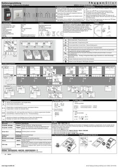
Program timer SC28.21 pro
Bedienungsanleitung D Schaltcomputer / Elektronische Schaltuhr müller SC 18.x0 easy / SC 28.x1 pro4 1. Sicherheitshinweise … Kanal … Kanal Anschlussbilder 3. Technische Daten Anschlussspannung Kontaktwerkstoff (115V / 230V) Kontaktwerkstoff (12V / 24V) Schutzart Umgebungstemperatur Wirkungsweise Verschmutzungsgrad Bemessungsstoßspannung Standard CFL, LED Siehe Gerät AgSnO2 AgNi IP 20 nach DIN EN 60529 -30°…+55° … BSTU … 4 kV DIN EN 60730-1/DIN EN 60730-2-7 Geeignet für moderne Leuchtmittel paladin 170 4x0 easy / 172 4x1 pro4 / 173 110 easy 2. Erstinbetriebnahme ! Einbau und Montage dürfen nur von einer Elektrofachkraft durchgeführt werden! Anderenfalls besteht Brandgefahr oder die Gefahr eines elektrischen Schlages! ! Nur an die auf dem Typenschild angegebene Spannung und Frequenz anschließen! ! Bei Eingriffen oder Änderungen an der Schaltuhr erlischt die Garantie! ! Die Schaltuhr ist so zu installieren, dass außergewöhnlich hohe Störstrahlung die Funktion nicht beeinträchtigen kann! Schaltuhr wird im Power-Fail-Modus ausgeliefert. Das Display ist Die aus. Drücken Sie die / Taste. Die Displayanzeige erscheint. Schaltuhr ist mit dem aktuellen Datum, der Uhrzeit und der Die europäischen Sommerzeitregel voreingestellt. Sie die gewünschte Sprache mit den -Tasten ein und Stellen bestätigen Sie mit . (Hinweis: Mit der -Taste können Sie jederzeit einen Schritt zurück) Uhrzeit und Sommerzeitregel falls nötig mit den Datum, einstellen und jeweils mit bestätigen. 4. Service 5. Bestimmungsgemäße Verwendung 6. Batterie Hugo Müller GmbH & Co KG Karlstraße 90 DE-78054 VS-Schwenningen +49 7720 80836 www.hugo-mueller.de Das Gerät ist zur Verwendung für folgende Aufgaben vorgesehen: Beleuchtungen im privaten und gewerblichen Bereich, Straßen- und Schaufensterbeleuchtung, Steuerung von Lüftungen, Motoren, Pumpen, Anlagen und Anwesenheitssimulation etc.. Das Gerät ist ausschließlich zum Einsatz in trockenen Räumen geeignet. Das Gerät ist nicht geeignet für sicherheitsrelevante Aufgaben, wie z.B. Fluchttüren, Brandschutzeinrichtungen etc. Verteilereinbau-Produkt: 7. Funktionsübersicht -Tasten 8. Symbolerklärung Kanal eingeschaltet / Programmierung EIN Kanal ausgeschaltet / Programmierung AUS erm Für das aktuelle Datum ist eine Ferien- / Datums-Schaltung aktiv. Aktueller Schaltzustand beruht auf einer programmierten Standardschaltzeit. erm I Akt. Schaltzustand beruht auf manueller Umschaltung des Programms und wird durch das gespeicherte Programm bei der nächsten Schaltzeit geändert. Akt. Schaltzustand beruht auf manueller Umschaltung und bleibt permanent erhalten, bis manuell zurückgesetzt wird. Wochentage Montag ... Sonntag; im Programmier-Modus zeigen Unterstriche an, welche Wochentage aktiviert sind. Aktueller Schaltzustand beruht auf einer Impuls-Schalzeit Schaltuhr ist über PIN gesperrt; PIN-Eingabe erforderlich. 9. Schaltzeit programmieren OK OK OK OK OK OK **Bei … KanalAusführung OK OK OK OK Automatik Modus erm 10. Tastenfunktion 11. Permanent / Zusatz-Schaltzeiten 1. Wechsel vom Automatik-Modus in den Eingabe-Modus. 2. Zurück-Funktion (Eine Ebene zurück). 1. Eingabe-Modus: Auswahlmöglichkeit zwischen verschiedenen Optionen . 2. Eingabe-Modus: Verändern der blinkenden Stelle. Permanent Ein / Aus Zyklus optional zuschaltbar h:mm:ss Einzeit (0:00:01 … 9:59:59) h:mm:ss Pause (0:00:01 … 9:59:59) Zusatz-Schaltzeiten optional zuschaltbar 1. Automatik-Modus: Ein- oder Ausschalten eines Kanals bis zur nächsten programmierten Schaltzeit. 2. Automatik-Modus: Tastendruck länger als … sec. = Permanentschaltung / 12. Zyklus / Zufall (1) Zufall optional zuschaltbar Nein Ja 1. Aktivieren der Schaltuhr durch Betätigen einer der Tasten (Ohne Netzspannung). 2. Bestätigen der Auswahl oder der Programmierung (Eine Ebene tiefer). 13. Weitere Einstellungen Menu-Punkt 14. Impuls Hauptmenu Anwendungen Programm Abfrage Programm Abfrage Schaltzeiten / Abfrage Speicherplatz Programm Löschen Programm Kanäle, einen Kanal oder einzelne Schaltzeiten zu löschen. Löschen der Schaltzeit(en). Sie haben die Möglichkeiten alle Datum-Zeit Einstellungen Einstellung Datum und Uhrzeit Sommerzeit Sprache Werkseinstellungen Einstellungen Sommerzeiteinstellungen Einstellungen Sprachauswahl Einstellungen Zurücksetzen auf Auslieferungszustand Zähler Optionen PIN-Code Optionen Programm -> Neu -> Kanal A/B -> … Die Impuls-Funktion bietet Ihnen die Möglichkeit eine Einschaltzeit mit festgelegter Schaltdauer zu programmieren. Die Uhr schaltet nach der programmierten Impuls-Dauer (Impuls bis zu 59:59 mm:ss) wieder aus. Die Programmierung erfolgt entsprechend einer normalen Standard Schaltzeit mit folgenden Unterschieden: Wählen Sie die Impuls-Funktion. Legen Sie die Einschaltdauer fest ( Impuls Minute / Impuls Sekunde). Legen Sie die Wochentage Ihrer Impuls-Schaltzeit fest Legen Sie die Einschaltzeit fest ( Zeit Stunde / Zeit Minute) 15. Programmierung über NFC (1) 16. Programmierung über Bluetooth (1) Anzeige der Betriebsstunden und Schaltungen je Kanal und für die Schaltuhr gesamt Sie können die Schaltuhr mit einem 4-stelligen PIN-Code sperren. Diesen Code können Sie bearbeiten, aktivieren oder deaktivieren. Sollten Sie ihn vergessen haben, wenden Sie sich bitte an unseren Kundendienst. Zusatz-Schaltzeiten: Programm -> Neue Schaltzeit -> Kanal A/B -> Zusatz Schaltzeit -> … Zusatzschaltzeiten ermöglichen Ihnen einzelne Schaltzeiten nach Datum zu programmieren. (1) Option www.hugo-mueller.de BA SC18x0easy SC28x1pro4 MP;de,en,fr,it -23692- 2019.07V05 Instruction Manual GB Time switch müller SC 18.x0 easy / SC 28.x1 pro4 1. Safety instructions … channels … channel Connection diagram 3. Technical data ! The installation and assembly of electrical equipment must be only carried out only by a skilled Person! Otherwise fire danger or danger of an electric shock exists! ! Connect the supply voltage/frequency as stated on the product label! ! Warranty void if housing opened by unauthorised person! ! The electronic circuit is protected against a wide range of external influences. Incorrect operating may occur if external influences exceed certain limits! 4. Service Supply voltage Contact material (115V / 230V) Contact material (12V / 24V) Type of protection Permitted ambiet temperature Mode of oeration Degree of contamination Rated surge voltage Standard CFL, LED See device AgSnO2 AgNi IP 20 to DIN EN 60529 -30°…+55° … BSTU … 4 kV DIN EN 60730-1/DIN EN 60730-2-7 Ideal for modern lamps Hugo Müller GmbH & Co KG Karlstraße 90 DE-78054 VS-Schwenningen +49 7720 80836 www.hugo-mueller.de 7. Menu overview paladin 170 4x0 easy / 172 4x1 pro4 / 173 110 easy 2. Initial operation The time switch is delivered in sleep-mode, the display is switched off. Press -/ button to wake it up. current date and time is already programmed and European daylight The savings time is activated. the desired language by pressing -buttons and confirm it by pressing Select . (Remark: By pressing you move one step backwards from the current position) required, date, time and daylight savings time mode can be adjusted also by Ifpressing -buttons and a subsequent confirmation with . 5. Intended use 6. Battery The device fits for the particular use of the following tasks: Illumination of private and industrial areas, street and shop-window lightening, regulation of air conditioning, flushing, motors, pumps, plants and machinery as well as to simulate presence etc. Operate the device in a dry room only! The installation must be in accordance with the instruction manual. The device is not qualified for security relevant tasks such as emergency doors, fire protection equipment DIN-rail mounting product: 8. Symbol legend Channel is switched ON Channel is switched OFF erm For the current date the “holiday program” / “permanent by date” is activated Standard programming step Current state is based on a manual over-ride. The state will be cancelled with the next programming step. erm I Current state is based on a manual over-ride. The state is permanent until terminated manuall. Days of the week Monday, Tuesday, ... Sunday; The underscores indicate if the program is active for the days above. Current state is based on a switching time with pulse function The time switch is locked; to unlock the device the PIN has to be entered . 9. New Program OK OK OK OK OK OK **At … channel version OK OK OK OK Automatic Mode erm 10. Key function 11. Permanent / Extra switching times Permanent On / Off 1. To access the Enter-mode (program, adjustments, options) from the automatic-mode. 2. To revert to the beginning of the current (sub-) menu. 1. To adjust the flashing digit. 2. To scroll through a choice 12. Cycle / Random (1) Cycle optionally selectable h:mm:ss on-time (0:00:01 … 9:59:59) h:mm:ss off-time (0:00:01 … 9:59:59) Extra switching times optionally selectable 1. Automatic-mode: To switch the channel ON or OFF until the next programming step occurs. 2. Automatic-mode: A push longer than … sec. = Permanent switching status. Random optionally selectable no / yes 1. To activate the time switch when operated without power supply. 2. To confirm the selection or the entered data. 13. Additional adjustments 14. Pulse Menu Main menu Application Program query Summertime Language To query the programming steps and remaining memory locations The pulse function provides you the opportunity of programming a switching time with a defined duration. As soon as the pulse-duration has expired the time switch switches OFF automatically (the duration of the pulse is up to 59:59 mm:ss). Deletion of switching time(s). The program for all channels, single The programming is carried out like a standard switching time (see point … / 9) with fo llowing differences Program channels and single programming steps within on channel can be Choose Pulse function (9F). deleted. Define the duration of the pulse ( pulstime minute / pulstime second). Program the days of the week Adjustment Adjustment of date and time Program the switching time ( time hour / time minute) Validation: Confirm the blinking summary of the pulse program 15. Programming via NFC (1) 16. Programming via Bluetooth (1) Adjustment Adjustment of the daylight saving time mode (ON/OFF) Adjustment Choice of languages Factory Defaults Adjustment Reset to the state of delivery. Program delete Date-Time Program -> New program -> Channel A/B -> … Program Counter Options PIN-Code Options Displays the hour counter and pulse counter for each channel and the time switch itself. The time switch can be locked with a 4-digit PIN-Code. The code can be adjusted, activated and deactivated. If you have forgotten the Code please call customer service. Extra switching time: Program -> new program -> channel A/B -> Extra switching time -> … These programming steps are single switching times by date. (1) Option www.hugo-mueller.de BA SC18x0easy SC28x1pro4 MP;de,en,fr,it -23692- 2019.07V05 Mode d´emploi F Interrupteur horaire müller SC 18.x0 easy / SC 28.x1 pro4 1. Instructions de sécurité … channels … channel Schéma de raccordement 3. caractéristiques ! L´ installation et le montage ne doivent être effectués que par les électriciens! Sinon il y a danger d´incendie ou d´électrocution. ! Strictement respecter les indications de tension et de fréquence mentionnées sur la plaque d´identité! ! Aucun droit de garantie en cas de manipulations et de modifications de l´appareil. ! L´interrupteur est à installer de telle façon que celui-ci ne soit pas soumis aux rayonnements pertubateurs pouvant nuire à sa fonction. 4. Service Supply voltage Contact material (115V / 230V) Contact material (12V / 24V) Type of protection Permitted ambiet temperature Mode of oeration Degree of contamination Rated surge voltage Standard CFL, LED See device AgSnO2 AgNi IP 20 to DIN EN 60529 -30°…+55° … BSTU … 4 kV DIN EN 60730-1/DIN EN 60730-2-7 Ideal for modern lamps Hugo Müller GmbH & Co KG Karlstraße 90 DE-78054 VS-Schwenningen +49 7720 80836 www.hugo-mueller.de 7. Sommaire des fonctions paladin 170 4x0 easy / 172 4x1 pro4 / 173 110 easy 2. Mise en service A sa fourniture, l´interrupteur horaire est à l´état de veille, l´affiche ur est etteint. Actionner la touche ./ pour activer l´appareil. La date et l´heure correspondent à la règle européenne pour l´horaire d´été. le langage souhaité avec les touches et valider avec . Sélectionner (Remarque:Avec la touche vous pouvez toujours revenir un pas en arrière) sélectionner la date, l´heure et la règle pour l´horaire d´été avec Silesnécessaire touches et valider en actionnant . 5. utilisation prévue 6. Battery The device fits for the particular use of the following tasks: Illumination of private and industrial areas, street and shop-window lightening, regulation of air conditioning, flushing, motors, pumps, plants and machinery as well as to simulate presence etc. Operate the device in a dry room only! The installation must be in accordance with the instruction manual. The device is not qualified for security relevant tasks such as emergency doors, fire protection equipment DIN-rail mounting product: 8. Légende des symboles Canal marche Canal arrêt erm Un programme vacances ou daté est activé pour la date actuelle. L´état actuel est basé sur un horaire de commutation standard. erm I L´état actuel est issu d´une commutation manuelle. Cet état sera modifié par le program me à la prochaine commutation. L´état actuel est basé sur une commutation manuelle. Cet état sera modifié p ar la prochaine action manuelle. Jours de semaine lundi … dimanche; les jours soulignés sont activés. L´état actuel correspond à une commutation par impulsion. L´interrupteur horaire est verrouillé; la connaissance du PIN est indispensable pour déverrouiller l´appareil . 9. Programmer une commutation OK OK OK OK OK OK **At … channel version OK OK OK OK Automatic Mode erm 10. Fonction des touches 11. Permanent / Commutation supplement Permanent Marche / Arret 1. Passage du mode automatique au mode entrée de données. 2. Fonction un pas en arrière 1. Mode entrée de données: Sélection de plusieurs options. 2. Mode entrée de données: déplacement de la position clignotante. Cycle sélection optionelle h:mm:ss Fermeture (0:00:01 … 9:59:59) h:mm:ss Pause (0:00:01 … 9:59:59) Commutation supplement sélection optionelle 1. Mode automatique: Marche/arrêt d´un canal jusqu´à la prochaine commutation programmée. 2. Mode automatique : Touche actionnée plus de … secondes = état permanent. / 12. Cycle / Random (1) Random sélection optionelle non oui 1. Activer l´interrupteur en actionnant la touche pendant plus de … seconde (appareil hors -tension) 2. Valider la sélection ou la programmation. 13. Autres réglages 14. Impulsion Menu principal Menu Programme demande Programme effacer Date-Heure Heure d été Langage Applications Programme -> Nouveau programme -> Canal A/B -> … La fonction impulsion permet de réaliser une commutation de durée determinée. A la fin de l´impulsion( Impulsion jusqu´à 59:59 mm:ss ), l´interrupteur horaire revient automatiquement à sa position initiale. Programme Heures de commutation / nombre de pas de programme La programmation est effectuée comme pour une commutation standard (voir point … / 9) avec les dérogations suivantes: Permet d´effacer le programme sur tous les canaux, ou sur un seul Programme canal ou seulement des pas de programme. Sélectionner la fonction Impulsion (9F). Déterminer la durée d´enclenchement ( impulsion minute / impulsion seconde). Programmer les jours de semaine Réglages Programmation de la date et de l´heure Programmer l´heure d´enclenchement ( Horaire heure / Horaire minute) Contrôle: Valider la commutation par impulsion clignotante 15. Programmation avec NFC (1) 16. Programmation avec Bluetooth (1) Réglages Réglage de l´horaire été / hiver Réglages Choix du langage Réglages usine Réglages Compteur Options PIN-Code Options Remise à zero, c´est à dire retour à l´état de livraison. Affichage des heures de marche et du nombre de commutations pour chaque canal et affichage du total de l´interrupteur horaire L´interrupteur horaire peut être verrouillé grâce à un code PIN de … chiffres. Ce code peut être modifié, activé ou désactivé. En cas d´oubli ou de perte de ce code, contacter notre service àprèsvente. Heures de commutation supplémentaires : Programme -> nouveau programme -> Canal A/B -> Heure de commutation supplément. -> … La fonction « heures de commutation supplémentaires » permet de réaliser des commutations uniques affectées à une date. (1) Options www.hugo-mueller.de BA SC18x0easy SC28x1pro4 MP;de,en,fr,it -23692- 2019.07V05 Manuale di istruzione I Interruttore orario müller SC 18.x0 easy / SC 28.x1 pro4 … channels 1. Consigli per l’installazione … channel Schema di collegamento 3. Specificazioni ! L’installazione ed il montaggio delle apparecchiature elettriche deve essere eseguito da personale esperto. Vi è un pericolo di infiammabilità e shock elettrico. ! Collegare l’apparecchiatura rispettando le indicazioni di tensione e frequenza indicate sul prodotto ! Se manomesso o modificato da personale non autorizzato, la Garanzia non ha effetto! ! Il circuito elettronico del dispositivo è protetto contro un’ampia gamma di distrurbi. Tuttavia, disturbi di livelli elevati potrebbero non far funzionare correttamente il dispositivo. 4. Service Supply voltage Contact material (115V / 230V) Contact material (12V / 24V) Type of protection Permitted ambiet temperature Mode of oeration Degree of contamination Rated surge voltage Standard CFL, LED See device AgSnO2 AgNi IP 20 to DIN EN 60529 -30°…+55° … BSTU … 4 kV DIN EN 60730-1/DIN EN 60730-2-7 Ideal for modern lamps Hugo Müller GmbH & Co KG Karlstraße 90 DE-78054 VS-Schwenningen +49 7720 80836 www.hugo-mueller.de 7. Descrizione del menù paladin 170 4x0 easy / 172 4x1 pro4 / 173 110 easy 2. Impostazioni iniziali dispositivo è impostato nella modalità STAND-BY ed il display è Ilspento. Premere il tasto / . data e l’ora corrente sono già impostate con le impostazioni La europee per il risparmio energetico la lingua desiderata premendo i tasti e confermare Selezionare premendo il tasto . (Attenzione: Premendo ci si sposta dalla posizione corrente a quella precedente) necessario, data, ora e la modalità del risparmio energetico Se possono essere impostate premendo i tasti confermando successivamente con il tasto . 5. Destinazione d'uso 6. Battery The device fits for the particular use of the following tasks: Illumination of private and industrial areas, street and shop-window lightening, regulation of air conditioning, flushing, motors, pumps, plants and machinery as well as to simulate presence etc. Operate the device in a dry room only! The installation must be in accordance with the instruction manual. The device is not qualified for security relevant tasks such as emergency doors, fire protection equipment DIN-rail mounting product: 8. Descrizione dei simboli Canale commutato nello stato ON Canale commutato nello stato OFF erm Funzionamento in modalità “programma vacanze” Funzionamento in base alla programmazione inserita Forzatura manuale. L’impostazione sarà modificata con il programma successivo. erm I Forzatura manuale. Lo stato permanente rimarrà fino al ripristino manuale. Giorni della settimana Lunedì, Martedì, …Domenica; Il trattino sotto il numero indica che quel giorno è programmato. E’ attiva una commutazione con la funzione Impulso Il dispositivo è bloccato; per sbloccarlo occorre digitare il codice PIN. 9. Nuovo programma OK OK OK OK OK OK **At … channel version OK OK OK OK Modo Automático erm 10. Descrizione tasti-funzione 11. Aggiungi programma / Fisso On / Off Fisso On / Off 1. Per accedere al menù (programma, impostazioni, opzioni) dalla modalità automatica. 2. Per tornare indietro, alla posizione precedente del menù . 1. Per impostare il dato che lampeggia 2. Per scorrere una selezionare selezionabile facoltativamente h:mm:ss Puntuale (0:00:01 … 9:59:59) h:mm:ss Pausa (0:00:01 … 9:59:59) Aggiungi programma selezionabile facoltativamente 1. Modalità automatica: commuta il canale in ON o OFF fino all’intervento del programma successivo. 2. Modalità automatica: premuto per … sec. = commuta nello stato permanente. / 12. Ciclo / Casuali (1) Ciclo Casuali selezionabile facoltativamente no si 1. Per attivare il display quando si opera senza alimentazione. 2. Per confermare la selezione o il dato inserito. 13. Impostazioni aggiuntive 14. Impulso Menu Menù principale Programma Verifica Programma Programma Elimina Programma Data-Ora Impostazioni Ora legale Lingua Impostazioni Impostazioni Impostazioni predefinite Impostazioni Ripristina le impostazioni iniziali. Contatore Opzioni PIN Opzioni Applicazione Programma -> Nuovo programma -> Canale A/B -> … La funzione impulso permette di impostare una programmazione con una durata di tempo specifica. Terminato l’impulso, il dispositivo commuta automaticamente in OFF (la durata dell’impulso arriva al massimo a 59:59 mm:ss). Per verificare le programmazioni e le posizioni di memoria libere Per la programmazione, vedere i punti … / … prestando attenzione alle seguenti differenze Cancella le programmazioni. Il programma per tutti i canali, singoli Scegliere la funzione Impulso (9F). canali e singole programmazioni, inserite all’interno del canale. Definire la durata dell’impulso ( Impulso minuti / Impulso secondi). Programmare i giorni della settimana Impostazione della data e dell’ora Impostare l’orario per la commutazione ( Ora ore / Ora minuti) Conferma: confermare il dato lampeggiante Impostazione dell’ora legale (ON/OFF) 15. Programmazione con NFC (1) 16. Programmazione con Bluetooth (1) Scelta della lingua Visualizza le ore e le commutazioni per ogni canale Il dispositivo può essere bloccato con un codice PIN a 4cifre. Il codice può essere impostato, attivato e disattivato. In caso ci si dimenticasse del PIN, occorre chiamare il servizio clienti Commutazioni Extra: -> -> -> Aggiungi Programma -> … Questi punti di programmazione sono singole commutazioni tramite data . (1) Opzioni www.hugo-mueller.de BA SC18x0easy SC28x1pro4 MP;de,en,fr,it -23692- 2019.07V05
(PDF | 1 MB)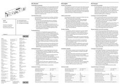
Installation instructions GEZE SecuLogic FTV 320 escape door lock
DE | Deutsch Produktbeschreibung EN | English Product description Die Fluchttürverriegelung FTV 320 ist Bestandteil des GEZE SecuLogic Rettungswegsystems und dient der Steuerung und Überwachung von elektrisch verriegelten Türen im Verlauf von Flucht-und Rettungswegen. Nach berechtigter Freischaltung oder durch Drücken der Nottaste der GEZE Türzentralen TZ 300 / TZ 320 entriegelt der FTV 320 die Tür elektrisch und gibt diese frei. Sicherheitshinweise GEZE FTV 320 DE Montagehinweise EN Installation instructions FR Consignes de montage Fluchttürverriegelung Emergency exit lock Verrou d‘issue de secours Germany GEZE GmbH Niederlassung Süd-West Tel. +49 (0) 7152 203 594 E-Mail: leonberg.de@geze.com GEZE GmbH Niederlassung Süd-Ost Tel. +49 (0) 7152 203 6440 E-Mail: muenchen.de@geze.com GEZE GmbH Niederlassung Ost Tel. +49 (0) 7152 203 6840 E-Mail: berlin.de@geze.com GEZE GmbH Niederlassung Mitte/Luxemburg Tel. +49 (0) 7152 203 6888 E-Mail: frankfurt.de@geze.com GEZE GmbH Niederlassung West Tel. +49 (0) 7152 203 6770 E-Mail: duesseldorf.de@geze.com GEZE GmbH Niederlassung Nord Tel. +49 (0) 7152 203 6600 E-Mail: hamburg.de@geze.com GEZE Service GmbH Tel. +49 (0) 1802 923392 E-Mail: service-info.de@geze.com Austria GEZE Austria E-Mail: austria.at@geze.com www.geze.at Benelux GEZE Benelux B.V. E-Mail: benelux.nl@geze.com www.geze.be www.geze.nl Bulgaria GEZE Bulgaria - Trade E-Mail: office-bulgaria@geze.com www.geze.bg China GEZE Industries (Tianjin) Co., Ltd. E-Mail: chinasales@geze.com.cn www.geze.com.cn GEZE Industries (Tianjin) Co., Ltd. Branch Office Shanghai E-Mail: chinasales@geze.com.cn www.geze.com.cn GEZE Industries (Tianjin) Co., Ltd. Branch Office Guangzhou E-Mail: chinasales@geze.com.cn www.geze.com.cn GEZE GmbH Reinhold-Vöster-Straße 21–29 71229 Leonberg Germany GEZE Industries (Tianjin) Co., Ltd. Branch Office Beijing E-Mail: chinasales@geze.com.cn www.geze.com.cn France GEZE France S.A.R.L. E-Mail: france.fr@geze.com www.geze.fr Hungary GEZE Hungary Kft. E-Mail: office-hungary@geze.com www.geze.hu Iberia GEZE Iberia S.R.L. E-Mail: info.es@geze.com www.geze.es India GEZE India Private Ltd. E-Mail: office-india@geze.com www.geze.in Italy GEZE Italia S.r.l E-Mail: italia.it@geze.com www.geze.it Scandinavia – Latvia GEZE Scandinavia AB Latvijas filiāle E-Mail: latvia@geze.com www.geze.lv Scandinavia – Lithuania GEZE Scandinavia AB Filial Lietu. E-Mail: lithuania@geze.com www.geze.lt Scandinavia – Sweden GEZE Scandinavia AB E-Mail: sverige.se@geze.com www.geze.se Scandinavia – Norway GEZE Scandinavia AB avd. Norge E-Mail: norge.se@geze.com www.geze.no Scandinavia – Denmark GEZE Danmark E-Mail: danmark.se@geze.com www.geze.dk Singapore GEZE (Asia Pacific) Pte, Ltd. E-Mail: gezesea@geze.com.sg www.geze.com GEZE Engineering Roma S.r.l E-Mail: italia.it@geze.com www.geze.it South Africa GEZE South Africa (Pty) Ltd. E-Mail: info@gezesa.co.za www.geze.co.za Korea GEZE Korea Ltd. E-Mail: info.kr@geze.com www.geze.com Switzerland GEZE Schweiz AG E-Mail: schweiz.ch@geze.com www.geze.ch Poland GEZE Polska Sp.z o.o. E-Mail: geze.pl@geze.com www.geze.pl Türkiye GEZE Kapı ve Pencere Sistemleri E-Mail: office-turkey@geze.com www.geze.com Romania GEZE Romania S.R.L. E-Mail: office-romania@geze.com www.geze.ro Ukraine LLC GEZE Ukraine E-Mail: office-ukraine@geze.com www.geze.ua Russia OOO GEZE RUS E-Mail: office-russia@geze.com www.geze.ru United Arab Emirates/GCC GEZE Middle East E-Mail: gezeme@geze.com www.geze.ae Scandinavia – Estonia GEZE Scandinavia AB eesti filial E-Mail: estonia@geze.com www.geze.ee Scandinavia – Finland GEZE Scandinavia AB Filial Finland E-Mail: finland@geze.com www.geze.fi United Kingdom GEZE UK Ltd. E-Mail: info.uk@geze.com www.geze.com Tel.: 0049 7152 203 … Fax: 0049 7152 203 310 www.geze.com The emergency exit lock FTV 320 is part of the GEZE SecuLogic emergency exit system and is used to control and monitor electrically locked doors on emergency exits. The FTV 320 unlocks the door electrically following authorised activation or by pushing the emergency push button on the GEZE door control units TZ 300 / TZ 320 and releases it. Safety instructions Für die Sicherheit von Personen ist es wichtig, nachstehenden Hinweisen Folge zu leisten. Diese Anweisungen sind aufzubewahren! à Die FTV 320 ist nach geltenden Normen und Bestimmungen geprüft und als geeignet anerkannt: EltVTR, EN 13637, EN 1670, EN 61000 à Die Montage an Feuer- und Rauchschutztüren ist nur erlaubt, wenn die Verwendbarkeitsnachweise für diese Türen dieses vorsehen und deren Maßgaben beachtet werden. à Es sind die Sicherheitshinweise des zugelassenen Rettungswegsystems zu beachten. Produkthaftung 159494-01 FR | Français Description du produit à Gemäß der im Produkthaftungsgesetz definierten Haftung des Herstellers für seine Produkte sind die hier enthaltenen Hinweise zu beachten. Die Nichtbeachtung entbindet den Hersteller von seiner Haftungspflicht. à Jede elektrische Verriegelung einer Tür im Verlauf eines Rettungsweges bedarf einer Befreiung von entgegenstehenden Vorschriften im Einzelfall. à Nur Sachkundige, die von GEZE autorisiert sind, dürfen Montagen, Funktionsprüfungen und Wartungen durchführen. à Es dürfen keinerlei mechanische oder elektrische Veränderungen vorgenommen werden. Auch das Entfernen oder Austauschen des Stulps schließt jede Haftung von GEZE für daraus resultierende Schäden aus. Montagehinweise Consignes de sécurité générales To ensure personal safety it is important to follow the notes below. These instructions must be kept. à The FTV 320 has been tested according to applicable standards and stipulations and found to be suitable: EltVTR, EN 13637, EN 1670, EN 61000 à Installation on fire and smoke protection doors is only permitted if the proofs of application suitability for these doors include this and their specifications are heeded. à The safety instructions for the approved emergency exit system must be followed. Product liability Technische Daten Pour la sécurité des personnes, il est essentiel de respecter les consignes suivantes. Ces instructions sont à conserver ! à Le FTV 320 est certifié selon les normes et dispositions applicables et reconnues comme adaptées : EltVTR, EN 13637, EN 1670, EN 61000 à Le montage sur des portes coupe-feu et pare-fumée n’est autorisé que si ces portes disposent d’une preuve de conformité et que les conditions prévues sont respectées. à Les consignes de sécurité du système pour issues de secours homologué doivent être respectées. Responsabilité du fait des produits à In compliance with the manufacturer’s product liability as defined in the German “Product Liability Act”, the instructions included here must be noted and followed. Failure to comply releases the manufacturer from his statutory liability. à Every electrical locking of a door on a rescue route must be exempted from contradictory regulations in individual cases. à Only specialists authorised by GEZE are permitted to carry out installation, function checks and after-sales service maintenance work. à No mechanical or electrical modifications may be made. GEZE shall not be liable for injuries or damage resulting from the removal or replacement of the front metal. Installation details à Die Montage der FTV 320 erfolgt DIN links, DIN rechts, waagerecht oder senkrecht, in Türblatt oder -rahmen. à Die abgeschrägte Seite der Steuerfalle muss beim Einbau in Schließrichtung zeigen. à Es ist darauf zu achten, dass keine Fremdteile oder Feilspäne in das Verriegelungselement gelangen. à Das Anwenden von Schmier- oder Gleitmittel ist untersagt. à Befestigungsschrauben sind nicht im Lieferumfang enthalten und müssen materialspezifisch ausgewählt werden. à Die Fallen der FTV 320 müssen ungehindert in das Schließblech greifen können, sodass die Tür einwandfrei schließt. à Es ist original GEZE-Zubehör zu verwenden. Le verrouillage pour issue de secours FTV 320 fait partie du système pour issues de secours GEZE SecuLogic et sert à commander et à contrôler les portes à verrouillage électrique dans les issues de secours. Une fois le déclenchement autorisé ou une fois le bouton de secours enfoncé sur la centrale de la porte GEZE TZ 300 / TZ 320, le système FTV 320 déverrouille la porte et la débloque. à Conformément à la responsabilité du fabricant vis-à-vis de son produit définie dans la loi relative à la responsabilité du fait des produits, les informations contenues dans le présent document doivent être respectées. Le non-respect libère le fabricant de son devoir de responsabilité. à Chaque verrouillage électrique d’une porte dans une issue de secours nécessite exonération des dispositions contraires au cas pas cas. à Seules les personnes qualifiées dûment autorisées par GEZE doivent réaliser les opérations de montage, de contrôle du fonctionnement et de maintenance. à Aucune modification mécanique ou électrique ne doit être apportée. Le retrait ou le remplacement de la battée libère GEZE de son devoir de responsabilité pour les dommages consécutifs. Consignes de montage à The FTV 320 is installed on the left hand (ISO 6) or right hand (ISO 5) side, horizontally or vertically, in the door leaf or frame. à The tapered side of the control latch must be pointing in the direction of closing movement when installed. à Care must be taken that no foreign material or filings get into the locking element. à The use of lubrication or gliding agents is prohibited. à Fixing screws are not supplied by GEZE and must be selected according to the specific material. à The latches of the FTV 320 must be able to engage freely in the strike plate so that the door can close perfectly. à Genuine GEZE accessories must be used. Technical data à Le montage du système FTV 320 peut être effectué selon DIN à gauche, selon DIN à droite, à l’horizontale ou à la verticale, dans le vantail de la porte ou dans le dormant. à Le côté biseauté du pêne de commande doit indiquer le sens de fermeture lors du montage. à Il est nécessaire de veiller à ce qu’aucune pièce externe et aucun élément de limaille ne se coince dans l’élément de verrouillage. à L’utilisation de graisse lubrifiante ou de lubrifiant est interdite. à Les vis de fixation ne sont pas fournies à la livraison et doivent être choisies de façon spécifique en fonction du matériel. à Les pênes du système FTV 320 doivent pouvoir s’insérer sans obstacle dans la tôle de fermeture afin que la porte puisse se fermer sans difficulté. à Des accessoires d’origine GEZE doivent être utilisés. Caractéristiques techniques Hauptmaße [mm] (B x H x T) Betriebsspannung [V DC] Stromaufnahme [mA] 15,2 x 138,8 x 37,3 24 +/- 15% Main dimensions [mm] (W x H x D) Operating voltage [V DC] Current consumption [mA] … x … x … 24 +/- 15% Dimensions [mm] (L x H x P) Tension de service [V DC] Consommation de courant [mA] 15,2 x 138,8 x 37,3 24 +/- 15% in verriegelten Zustand kurzzeitig bei Verriegelungsvorgang Betriebstemperatur [°C] 110 290 -20/+60 in locked state briefly during the locking process Operating temperature [°C] 110 290 -20/+60 dans un état verrouillé À court terme lors du processus de verrouillage Température de service [°C] 110 290 -20/+60 Eignungsnachweis EltVTR/EN 13637 Suitability certificate EltVTR/EN 13637 Certificat de conformité EltVTR/EN 13637 Aufbruchfestigkeit [N] … Break-open resistance [N] … Résistance à la rupture [N] … Fallenvorlast [N] … Latch sideload [N] … Précontrainte du pêne [N] … Spaltmaß [mm] 5±2 Gap dimensions [mm] 5±2 Écartement de la fente [mm] 5±2 Weitere Informationen und Support im Internet unter www.geze.com Visit www.geze.com for further information and support. Plus d‘informations et de conseils sur Internet sur www.geze.com TZ 300 TZ 320 FTV 320 FTV 320 TZ 300 TZ 320 FTV 320 FTV 320 Li-Y(ST)Y … x 0,25 mm2, max. 100 m B B C 20 18 24 22 J-Y(ST)Y … x … x 0,6 mm, max. 100 m TZ 300 / TZ 320 FTV 320 X101 / X106 (orange) + … 5 - … 6 verriegelt / locked / verrouillé 14 24 V DC … 14 Verriegelungszustand Locking mode … État du verrouillage geschlossen / closed / fermé 15 Verriegelung Locking Verrouillage + 24 V - GND Eingang / Input / Entrée COM1 15 Türzustand Door mode … État de la porte COM2 … COM1 SA Sabotage … 1 NO NO optional / en option … 52 53 … 2 NO 2x 5×35 2x M5×20 … 2
(PDF | 2 MB)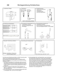
Toplock
D 1. Vorbereitung F Türflügel GB I Montageanleitung Schaltschloss 2. Befestigung Blechschraube ST 4,2 x 13mm DIN 7982 Schraube M5 x 12mm DIN 965 3. Schaltschlossachse senkrecht über Achse des Gewindelochs (Treibriegelschloss, Anti-Panik-Gegenkasten) Blindnietmutter M5 nicht im Lieferumfang enthalten 4. Ermittlung der Stangenlänge L Panikgegenkasten Vollblatt Panikgegenkasten Vollblatt mit Stangenantrieb IQ AUT Panikgegenkasten lang Panikgegenkasten lang mit Stangenantrieb IQ AUT L = X - 41 L = X - 604 Panikgegenkasten kurz Panikgegenkasten kurz mit Stangenantrieb IQ AUT L = X - 73 L = X - 636 5. Einschlagen des Gleitstopfens nur im „nichtmontierten“-Zustand. Gewinde am Stangenende nicht beschädigen! 6. Treibriegelstange eindrehen und Schaltschloss montieren. Bei der Montage der Treibriegelstangen muss das Anzugsdrehmoment … - … Nm betragen. 8. Ausrichtung des Schaltschlosses 9. Funktionsprobe L = X - 126 L = X - 672 3-6 mm 7. Bei großer Türluft Stulp unterfüttern Achtung: Schließblech im Bereich des Fallenaufschlages anfasen Zum Einbau des Schaltschlosses dürfen nur Artikel verwendet werden, welche in der Montageanleitung beschrieben sind. Die Anleitungen bzw. Anweisungen müssen vom Monteur an den Benutzer weitergegeben und von diesem bis zum Ende der Nutzung aufbewahrt werden. 1. Die Flügel und der Rahmen des Türelementes müssen aus ausreichend stabilen Werkstoffen (z.B. geschweißter Stahl oder Aluminiumprofil) bestehen. Die Verformung des Türelementes ist so gering zu halten, dass die Funktion der Verschlusselemente nicht beeinträchtigt wird. 2. Es dürfen nur Elemente erstellt werden, deren Flügelhöhe von 3000 mm, Flügelbreite von 1500 mm und Flügelgewicht von 300 kg nicht überschritten wird. 3. Das Verschlusssystem ist nach Feuerwiderstandsklasse EI60 (T60) in zweiflügeligen Stahl- und Aluminiumtüren geprüft. Bei Verklemmung, siehe Abb. … und … 4. Schlüsselbetätigte Halb- oder Doppelzylinder sowie mechanische oder elektronische Knaufzylinder, mit oder ohne Schlüsselbetätigung, haben keinen Einfluss auf die Paniktürfunktion des Schlosses (auch bei steckendem Schlüssel). Lediglich der Knauf eines mechanischen oder elektronischen Knaufzylinders kann in Abhängigkeit von der Knaufform und –größe die Funktion der Stangengriffe beeinflussen. Bei einigen Stangengriffen ist die Gefahr durch Quetschoder Scherstellen gegeben. Deshalb ist es wichtig, dass zwischen der Außenseite des Knaufs bis zum Hebelarm des Stangengriffs, oder eines anderen auslösenden Beschlagteils, ein Freiraum von mindestens 10 mm sichergestellt wird. D GB Installation instructions for switching lock F1. PreparationIof door leaf 2. Fixing self lapping screw screw ST 4,2 x 13mm M5 x 12mm DIN 7982 DIN 965 3. Align axle of switching lock perpendicularly above axle of tapped hole (espagnolette lock, panic keep) riv nut M5 not included 4. Determining the length (L) of the shoot bolt Panic keep full leaf Panic keep full leaf with rod drive IQ AUT Panic keep long Panic keep long with rod drive IQ AUT L = X - 41 L = X - 604 Panic keep short Panic keep short with rod drive IQ AUT L = X - 73 L = X - 636 5. Drive in sliding stopper only in unscrewed status. Do not damage the thread at the end of the bolt 6. Turn shoot bolt in and mount switching lock. During mounting the shoot bolts the locking torque has to be 5-8 Nm. 8. Align switching lock 9. Function test L = X - 126 L = X - 672 3-6 mm 7. Shim forend if there is more door clearance Attention: Chamfer striking plate where latch bolt hits Only use articles which are describe in these instructions. These instructions and directions should be passed to the end user by the installer and keep reliably up to the end of the working life. 1. The leaves and the frame of the door element must be made of sufficiently sturdy materials (e.g. welded steel or aluminum profile). Make sure that any deformation in the door element is kept to a minimum to ensure that the locking element will work properly. 2. The leaf dimensions in the door elements produced may not exceed 3000 mm in height, 1500 mm in width or 300 kg in weight. 3. The locking system complies with fire rating EI60 (T60) for double-leaf steel and aluminum doors. If jammed, see point … and … 4. Key-operated half- or double cylinders as well as mechanical or electronic knob cylinder (with or without key operation) have no effect on the lock’s panic door function (even when the key is inserted). Only the knob of a mechanical or electronic knob cylinder can affect the push bar’s functioning, depending on the knob shape and size. Some push bars pose the risk of pinch or shearing points. That’s why it’s important to keep a clearance of at least 10mm between the outside of the knob up to the lever arm or other activating fitting. Leaving technical details.
(PDF | 634 KB)